Assembly (continued), A warning – Troy-Bilt 13039-16HP User Manual
Page 3
Attention! The text in this document has been recognized automatically. To view the original document, you can use the "Original mode".
Assembly (continued)
Rear Wheels
□ Hoist or jack rear of unit at rear hitch
high enough to allow rear wheels to slide
onto wheel hubs (Z, Fig. 2).
A WARNING
USE EXTREME CARE WHEN JACKING OR
HOISTING TRACTOR. BLOCK WHEELS
AND USE JACKSTANDS TO SECURELY
HOLD UNIT IN PLACE.
□ Grease studs on rear wheel hubs with
multi-purpose grease.
□ Position wheels (F) with valve stems to
the inside on studs in hub (Z).
□ Secure wheels to hubs with lug nuts
(M) with 3/4” socket wrench. Torque to 45
ft-lbs. Position lug nuts on studs with
tapered ends to the inside.
□ Install hub caps (E).
Front Wheels
□ Securely block rear wheels to prevent
tractor from rolling.
□ Hoist or jack front of unit high enough
to allow front wheels to slide onto wheel
spindles. If a jack is used, jack at center
point of front axle.
□ Slide wheels (A, Fig. 1) with valve
stems to the inside and washers (B and C)
onto wheel spindles.
Note: Use washers
(C) as required to take up slack.
□ Using retaining ring pliers, secure
wheels with retaining rings (D).
□ Install hub caps (E).
Tire Pressure
□ Use air pressure gauge to check tire
pressure. Adjust as necessary.
FRONT TIRES: 12-14 PSI (82-96 kPa)
REAR TIRES: 8-10 PSI (55-69 kPa)
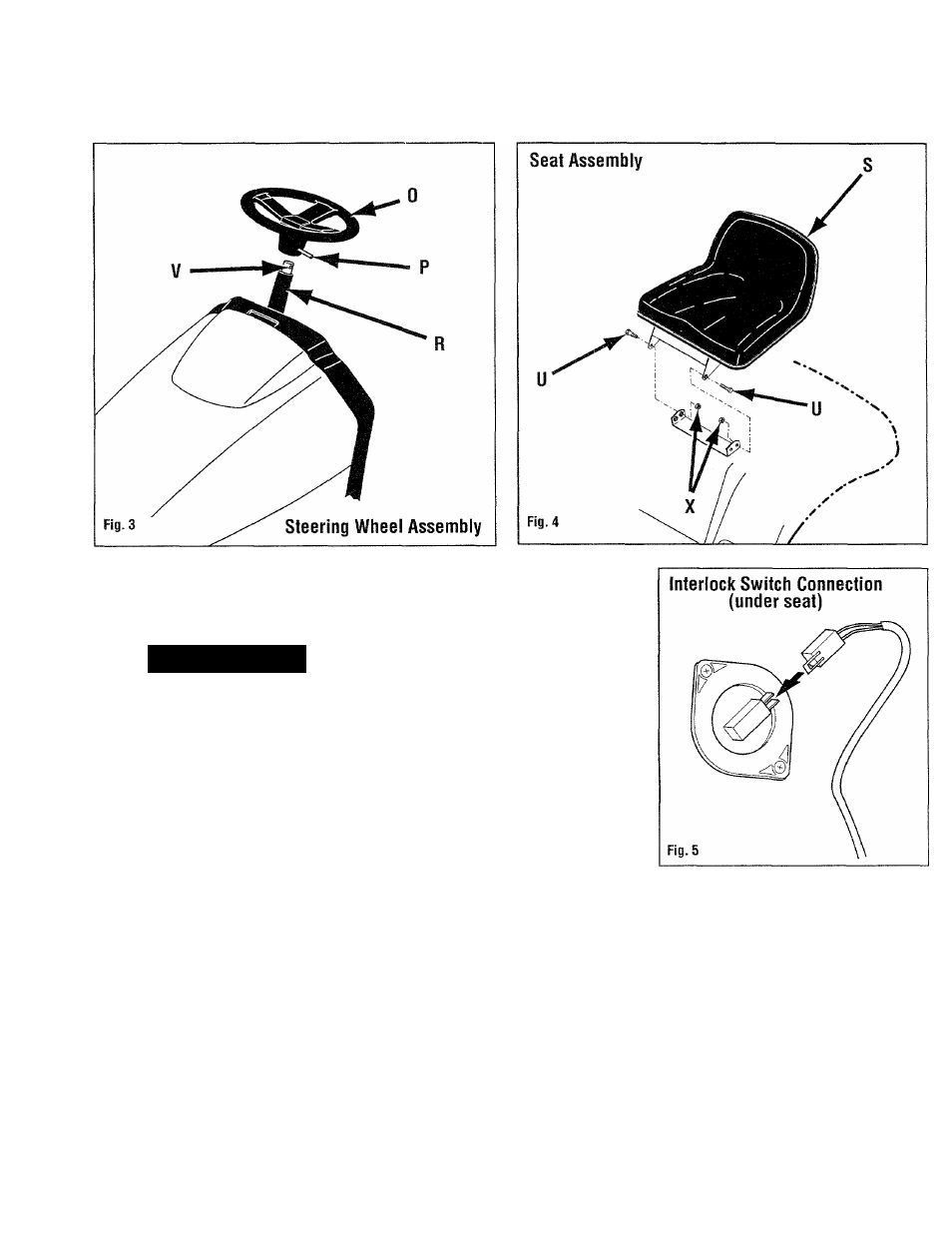
Steering Wheel
□ Align front wheels of unit so they point
straight ahead.
□ Place steering wheel (0, Fig. 3) with
roll pin (P) over steering column (R).
Rotate steering wheel as shown.
□ Align steering wheel on steering shaft
(V) as follows: place drift pin in hole
opposite roll pin in steering wheel. Rotate
steering wheel until drift pin slides into
mating hole in steering shaft.
□ Secure steering wheel by tapping roll
pin (P) with hammer until it is completely
inside steering wheel.
Seat
□ Place seat assembly (S, Fig. 4) onto
seat bracket.
□ Using a 9/16” socket and a 9/16” open-
end wrench, secure seat with screws (U)
and nuts (X) at desired hole in seat
bracket.
Note: Operators with inseam
lengths 30" (or shorter) to 38” should
use front hole in seat bracket; operators
with inseam lengths 38” and over
should use rear hole in seat bracket.
□ Plug seat interlock lead (Fig. 5) into
interlock switch on bottom of seat.