Board overview, Table 1: flashdrive/104 components, Figure 1: flashdrive/104 layout – Connect Tech 104 User Manual
Page 6: See section 1
Connect Tech FlashDrive/104 User's Manual
Revision 0.08
2
Board Overview
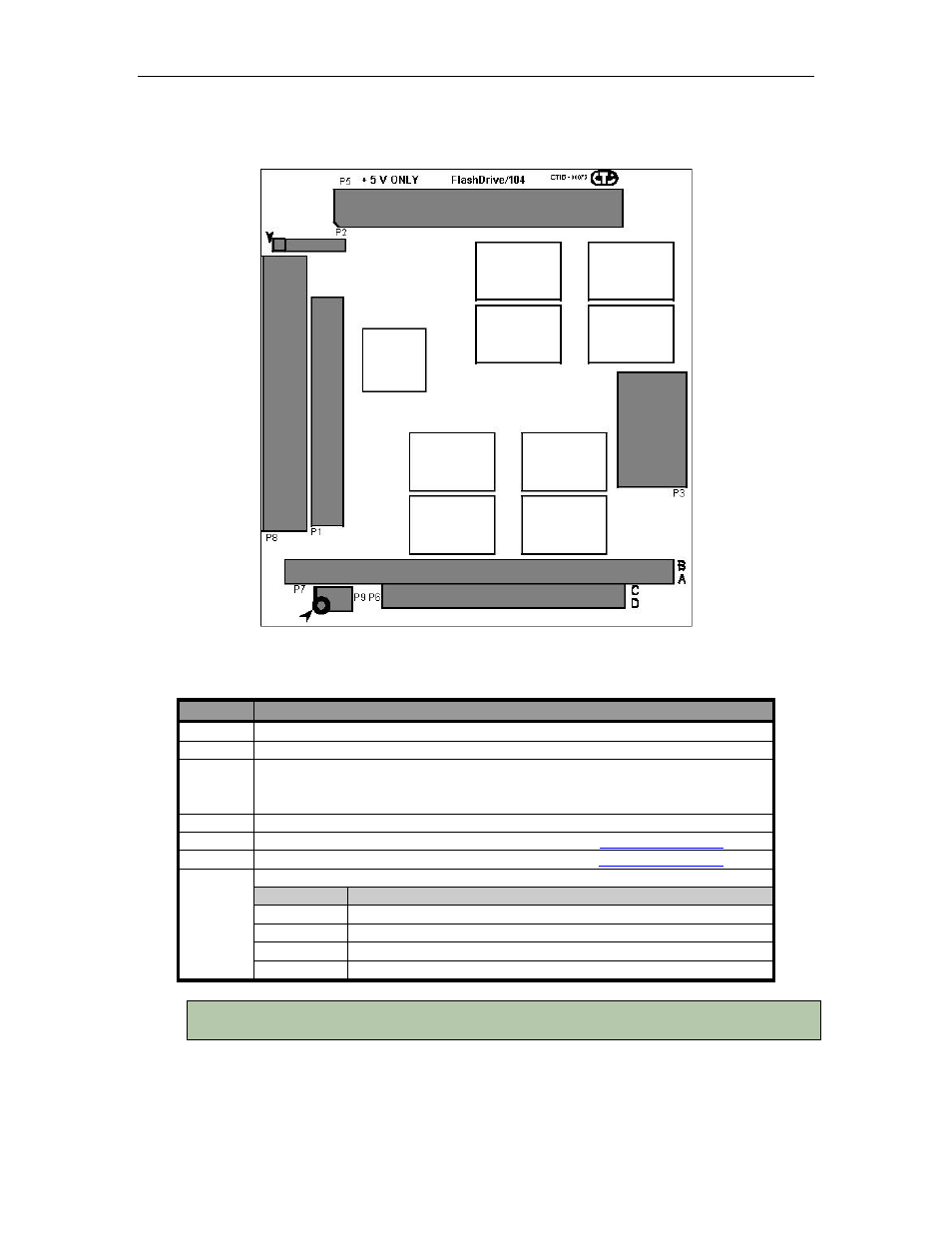
Figure 1: FlashDrive/104 Layout
Table 1: FlashDrive/104 Components
Location
Description/Function
P9
Master / Slave Selection and Write Protect
P8
ATA/IDE 0.100” Connector
P1
ATA/IDE 2mm Connector
DDG/ DEG: pins 41 & 42 are connected to 5V
DGG: pins 41 & 42 are not connected
P2
Diagnostic Header (Connect Tech use only)
P6, P7
PC/104 Connector – specifications available from th
P5
PCI-104 Connector -specifications available from th
P3
Power Connector:
Pin
Signal
1
N/C (+12 V on cable)
2
N/C (GND on cable)
3
GND
4
+5V
NOTE: P5, P6 and P7 are used with mechanical stack throughs only. P3 provides power over
standard PC disk drive power connectors (5V only)