Locked dial setting or limited setting stops, Caution, Installation – White Rodgers 1A10 User Manual
Page 3
Attention! The text in this document has been recognized automatically. To view the original document, you can use the "Original mode".
LOCKED DIAL SETTING OR LIMITED SETTING STOPS
The enclosed stops may be used to provide “LOCKED DIAL
SETTING” or “LIMITED SETTING”. Instructions for
installing the stops to perform either of these functions are
given below.
NOTE:
Once stops are installed, they cannot be removed.
CAUTION
To prevent electrical shock and/or
equipment damage, disconnect electric power to system,
at main fuse or circuit breaker box, until installation is
complete.
PACKAGE CONTAINS:
2 — stops
2 — pins
STOP
PIN
INSTALLATION
MAXIMUM LIMIT DIAL SETTING
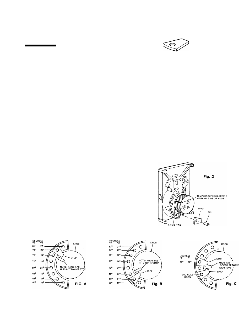
— By installing one Stop,
the maximum limit temperature may be set. (Example: Fig. A,
Max. Limit Setting 78° F or 26°C)
1. From Figure “A” select the hole at the outer edge of the
knob which corresponds to the maximum dial setting you
desire.
2. Rotate knob counter-clockwise to lowest setting. Remove
thermostat cover by grasping top and bottom and pull
straight out.
3. Position stop under knob so the hole in the stop and
selected hole in thermostat base are aligned. Insert pin
into aligned holes, but do not push pin completely down.
(Fig. ”D”)
4. Rotate knob clockwise to its newly selected maximum
setting. With the thermostat cover in place, this should
now be the maximum temperature setting you selected in
step #1. If setting is incorrect, the stop is still removable
and may be moved to another hole.
5. With stop installed in the correct hole, the pin can now be
seated down on the stop by pushing with the blade of a
screwdriver or gently tapping with a light object. Use care
not to hit the knob.
The stop is now installed and cannot
be removed.
MINIMUM LIMIT DIAL SETTING
— By Installing one Stop,
the minimum temperature may be set. (Example: Fig. B, Min.
Limit Setting 69°F or 21°C)
1. From Figure “B” select the hole at the outer edge of the
knob which corresponds to the minimum dial setting you
desire.
2. Rotate knob clockwise to highest setting. Remove
thermostat cover by grasping top and bottom and pull
straight out.
3. Position stop under knob so the hole in the stop and
selected hole in thermostat base are aligned, insert pin
into aligned holes but do not push pin completely down.
(Fig. D)
4. Rotate knob counter-clockwise to Its newly selected
minimum setting. With the thermostat cover in place, this
should now be the minimum temperature setting you
selected in step #1. If setting is incorrect, the stop is still
removable and may be moved to another hole.
5. With stop installed in the correct hole, the pin can now be
seated down on the stop by pushing with the blade of a
screwdriver or gently tapping with a light object. Use care
not to hit the knob.
LOCKED DIAL SETTING
— By installing two Stops, the
Knob may be locked at a selected temperature (Fig. C).
1. Select the temperature setting at which the knob is to be
locked and locate the corresponding hole in fig. “A”
(Minimum 66°F or 19°C, Maximum 81°For 27°C). Install
the first stop as described In maximum limit dial setting
section.
2. Rotate the knob clockwise until It hits the first stop. Install
the second stop in the same manner In the second hole
down from first stop. (Example: Fig. C Knob setting is
locked at 72°F or 22°C and cannot be changed.)
MAX. DIAL SETTING STOP
MIN. DIAL SETTING STOP
LOCKED DIAL SETTING