White Rodgers 1F51 User Manual
White-rodgers, Automatic controls
Attention! The text in this document has been recognized automatically. To view the original document, you can use the "Original mode".
WHITE-RODGERS
AUTOMATIC CONTROLS
TYPE 1D51 and 1F51
Low Voltage
COOLING ASTRO^STATS
with Sub-Base for System and Fan Selection
- INSTRUCTIONS -
These low voltage thermostats are designed for operation of
the cooling system. A selector switch provides convenient
selection of cooling system and blower operation. These
thermostats are equipped with a fixed type cooling anticipator
to p r o v i d e
f o r
n a r r o w differential control of room
temperature. Models are available with either sealed mercury
contacts, or with snap-action contacts.
■ SELECTING THERMOSTAT LOCATION
The proper location of the room thermostat is most important
to insure that it will provide a comfortable home temperature.
Observe the following general rules when selecting a location:
1. Locate it about 5 ft. above the floor.
2. Install it on a partitioning wall, not on an outside wall.
3. Never expose it to direct light from lamps, sun, fireplaces,
etc.
4. Avoid locations close to doors that lead outside, windows,
or adjoining outside walls.
5. Avoid locations close to radiators, warm air registers, or in
the direct path of heat from them.
6. Make sure there are no pipes or duct work in that part of
the wall chosen for the thermostat location.
7. Never locate it in a room that is warmer or cooler than the
rest of the home, such as kitchen or hallway.
8. The living or dining room is normally a good location,
provided there is no cooking range or refrigerator on
opposite side of wall.
INSTALLATION
Attaching Sub-Base to Wall
1. Route wires from cooling equipment to thermostat location
and pull wires through hole in wall so that 6 in. of cable
protrudes.
2. Puli wires through opening near center of sub-base and
connect wires beneath proper terminals screws as shown
under "wiring".
3. Push excess wire into wall or switch box and plug up hole
to prevent drafts from affecting thermostat operation.
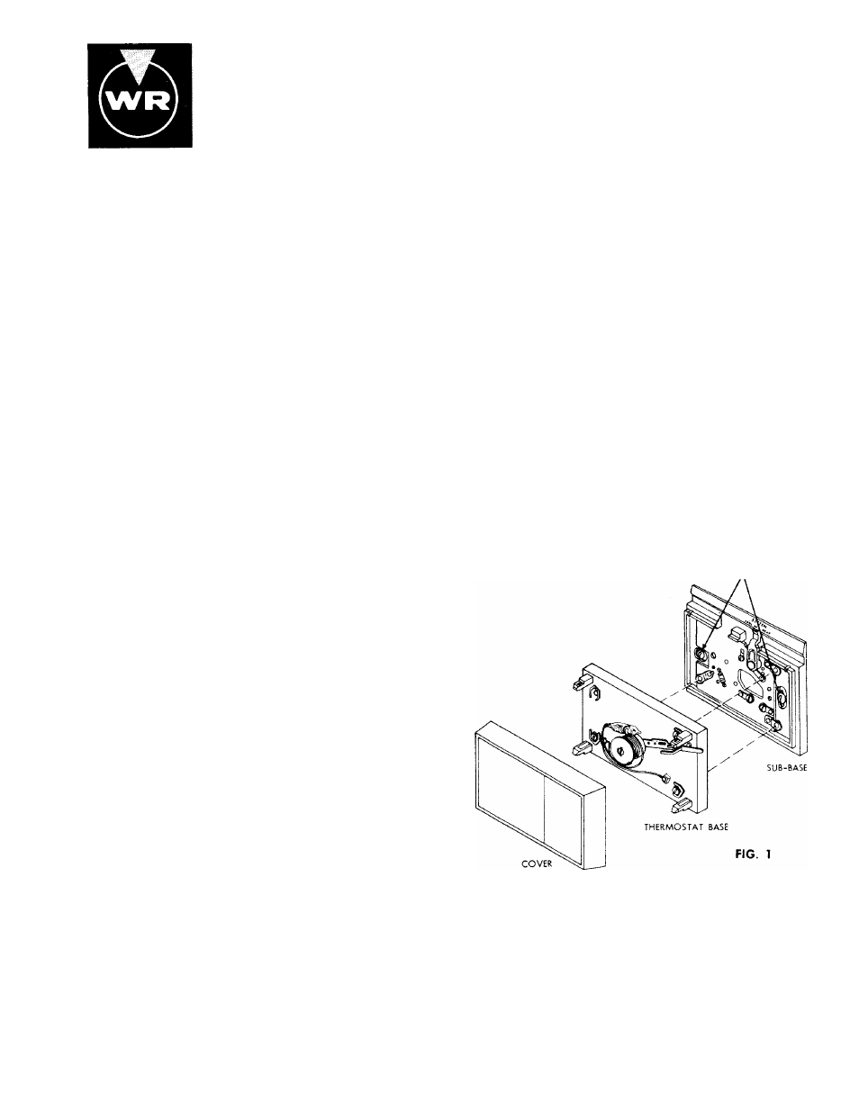
4. Fasten sub-base loosely to wall in position shown in Fig. 1
using two mounting screws provided. Level sub-base by
placing spirit level on top of sub-base. Tighten mounting
screws to secure sub-base in level position.
Mounting Thermostat to Sub-Base
1.
Remove cover from thermostat by pulling it straight
outward.
2. Attach thermostat base to sub-base, being sure that all
screws are tightened snugly since they serve as electrical
connections between thermostat and sub-base.
3. Snap on thermostat cover and set thermostat to desired
setting.
MOUNTING SCREWS
COOLING ANTICIPATION
This thermostat is equipped with a fixed non removable
heater. It is for use on current draws from 0 to 1.5 Amp.
I
WHITE-RODGERS DIVISION
EMERSON ELECTRIC CO.
9797 REAVIS ROAD
ST. LOUIS, MISSOURI 63123
Printed in U.S.A.
PART No. 37-2223
IsMIERSDN