Replacing "old style” flame sensors (continued) – White Rodgers F145-0825 User Manual
Page 2
Attention! The text in this document has been recognized automatically. To view the original document, you can use the "Original mode".
REPLACING "OLD STYLE” FLAME SENSORS (continued)
B. Oil Line-Mounted Flame Sensor (Fig. 6)
1. Observe flame sensor position and mark location of Cad
Cell on the oil line for reference as shown in Fig. 6. Then
remove and discard the entire Flame Sensor by
removing screw holding mounting bracket to the oil line.
2. Assemble new 956-128 Flame Sensor as shown in Fig.
2
.
3. Install new Flame Sensor to oil line taking care to locate
mounting bracket so that Cad Cell of new Flame Sensor
will have same view of the oil flame as the old Flame
Sensor (use reference mark on oil line). Be sure screw is
securely tightened.
4. Reconnect leads of Flame Sensor to primary control,
being sure that leads are clear of blower wheel.
5. Close ignitign transformer, being sure Flame Sensor
leads are clear of cover. Restore electric power and
check burner for proper operation.
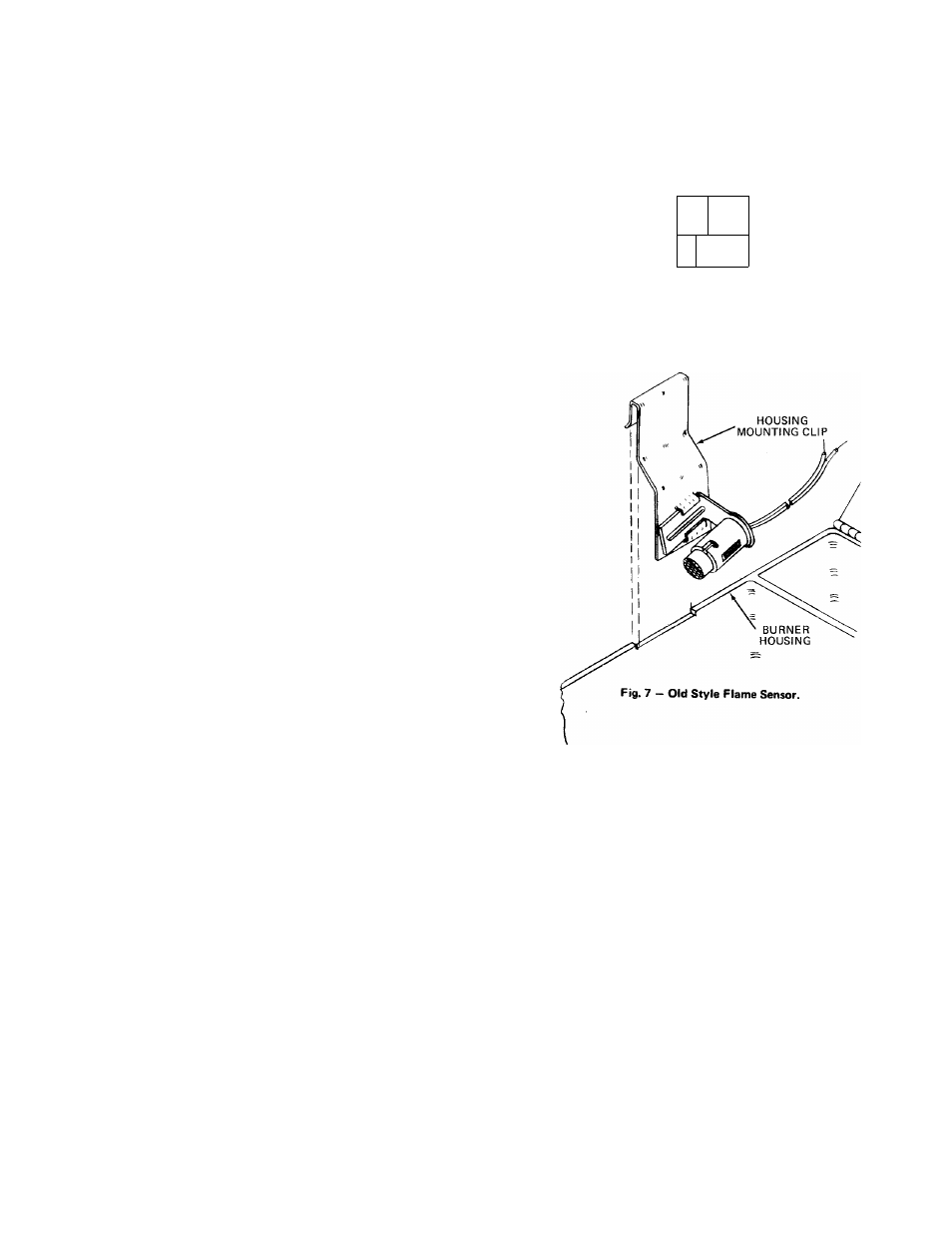
C. Flame Sensor Mounted on Side of Burner Housing (Fig. 7)
1. Remove Housing Mounting Clip from side of burner
housing as shown in Fig. 7. Then remove and discard old
Flame Sensor from Housing Mounting Clip.
2. Assemble new 956-133 Flame Sensor as shown in Fig. 3.
3.
Insert bracket of new Flame Sensor into Housing
Mounting Clip. Then replace Housing Mounting Clip on
side of burner housing.
4. Reconnect leads of Flame Sensor to primary control,
being sure that leads are clear of blower wheel.
5. Close ignition transformer, being sure Flame Sensor
leads are clear of cover. Restore electric power and
check burner for proper operation.
OIL LINE
\
■71
OF CAD CELL
CELL -
unn
______P
FLAME SENSOR
Fig. 6 — Old Style Flame Sensor.