Sears CPCRKHTR004A00 User Manual
Page 2
Attention! The text in this document has been recognized automatically. To view the original document, you can use the "Original mode".
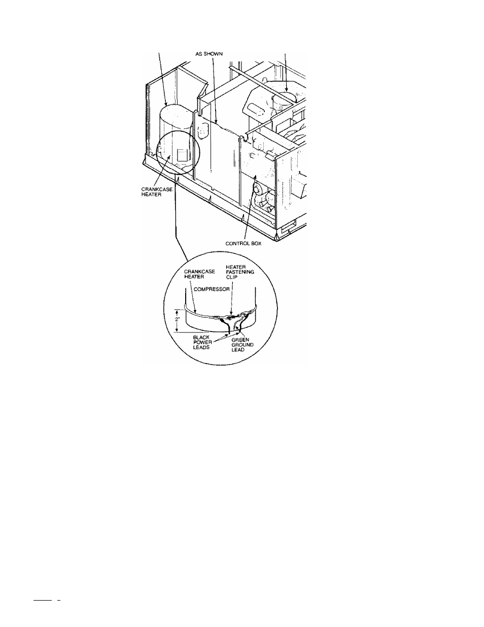
( NOTE; TOP CONDENSER SECTION NOT SHOWN )
COMPRESSOR
ROUTE WIRES
IMDOOR FAN MOTOR
C01015
Fig. 1—^Typical Crankcase Heater Installation
CH
-BLK-
-BLK-
LEGEND
C
— Compressor Contactor
CH — Crankcase Heater
Marked Terminal
C01014
7. Connect one black lead to the compressor contactor terminal
11, and connect other black lead to compressor contactor
terminal 21. (See Fig. 2.)
8. Attach green crankcase heater ground lead to ground screw in
control box.
Copyright 2001 Carrier Corporation
Fig. 2—Crankcase Heater Wiring
9. Replace access panel.
10. Turn on main power, then (if applicable) gas supply.
5S2a1812
Manufacturer reserves the right to discontinue, or change at any time, specifications or designs without notice and without incurring obligations.
gool<| 1
I
4 PC 101 Catalog No. 534-800S5 Printed in U.S.A. Form 48/50-102SI
Pg 2
5-01 Replaces: 48GS,GX-3SI
Tab |4a]la