Pump rotor, continued), Specifications wiring diagrams – Sears 583.35683 User Manual
Page 14
Attention! The text in this document has been recognized automatically. To view the original document, you can use the "Original mode".
(Pump Rotor, continued)
10.
Install blades, pump plate, air
filters, and filter end cover.
11.
Replace fan guard and upper shell.
12.
Adjust pump pressure (see page 11).
Note: If rotor is still binding, proceed
as follows:
13.
Perfonn steps 1 thru 6 (see page 13).
14.
Place fine grade sandpaper (600
grit) on flat surface. Sand rotor
lightly in “figure 8” motion four
times (see Figure 29).
15.
Reinstall insert and rotor.
16.
Perform steps 10 thru 12 above.
SPECIFICATIONS
WIRING
DIAGRAMS
Gap Adjusting Screw
Blade
I .0037.004" Gap
^ Measured With
Feeler Gauge
Sandpaper
Rotor
Gap Adjusting Screw
Figure 28 - Gap Adjusting Screw Locations
Figure 29 - Sanding Rotor
Output Rating (Btu/Hr.)
Fuel
Fuel Tank Capacity (U.S. Gal.)
Fuel Consumption (Gal. Per Hr.)
Electric Requirements
Amperage (Normal Run)
Hot Air Output (CFM)
35.000
55,000
110,000
Use Only Kerosene or No. 1 Fuel Oil
3.0
5.0
9.0
.26
.40
.82
120 V/60 Hz (Same All Models)
2.0
2.0
4.5
165
175
490
Power Plug
120V/60HZ
Reset
' Button
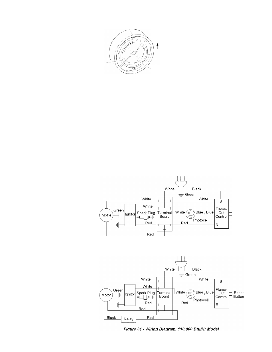
Figure 30 - Wiring Diagram, 35/55,000 Btu/Hr Modeis
Power Plug
120V/60HZ