Preparatron, Installation – Sears 233.52053 User Manual
Page 4
Attention! The text in this document has been recognized automatically. To view the original document, you can use the "Original mode".
PREPARATrON
1. Use the dimensional drawings (Refer to FIGURES 1 - 3) to lay
out the range hood’s mounting holes, wiring access and ductwork
by marking the cabinet bottom and drywall where applicable.
2. Make cutouts for wiring and ductwork.
3. If the hood is to be ducted, install the ductwork so that is flush to
the range hood’s mounting surface.
Refer to FIGURE 1 if the range hood is to be installed with a
horizontal discharge.
Refer to FIGURE 2 and FIGURE 3 if the range hood is to be
installed with a vertical discharge.
4. Run two-conductor wire (with ground) from a power source to
the hood location. Bring approximately 12”of wiring through wir
ing hole in cabinet.
5. Drill four 3/52” diameter pilot holes at points where mounting
holes are marked in cabinet bottom.
6. Insert four (4) mounting screws, leaving approximately W” of
thread exposed.
7. Remove and retain the mounting screws securing the 3W”x 10”
and 7" duct transitions to the hood. Install the appropriate duct
transition as described in the installation section.
INSTALLATION
1. Remove the necessary duct opening and wiring knockout from
the range hood.
If the range hood is to be installed as a non-ducted unit, re
move the wiring knockout only.
If the range hood is to be installed as a ducted unit, a baffle
plate is provided to close off the non-ducted vent. InstaU baffle
plate (Refer to FIGURE 4) by sliding into place behind grille. Use
locator bumps to orient in grille.
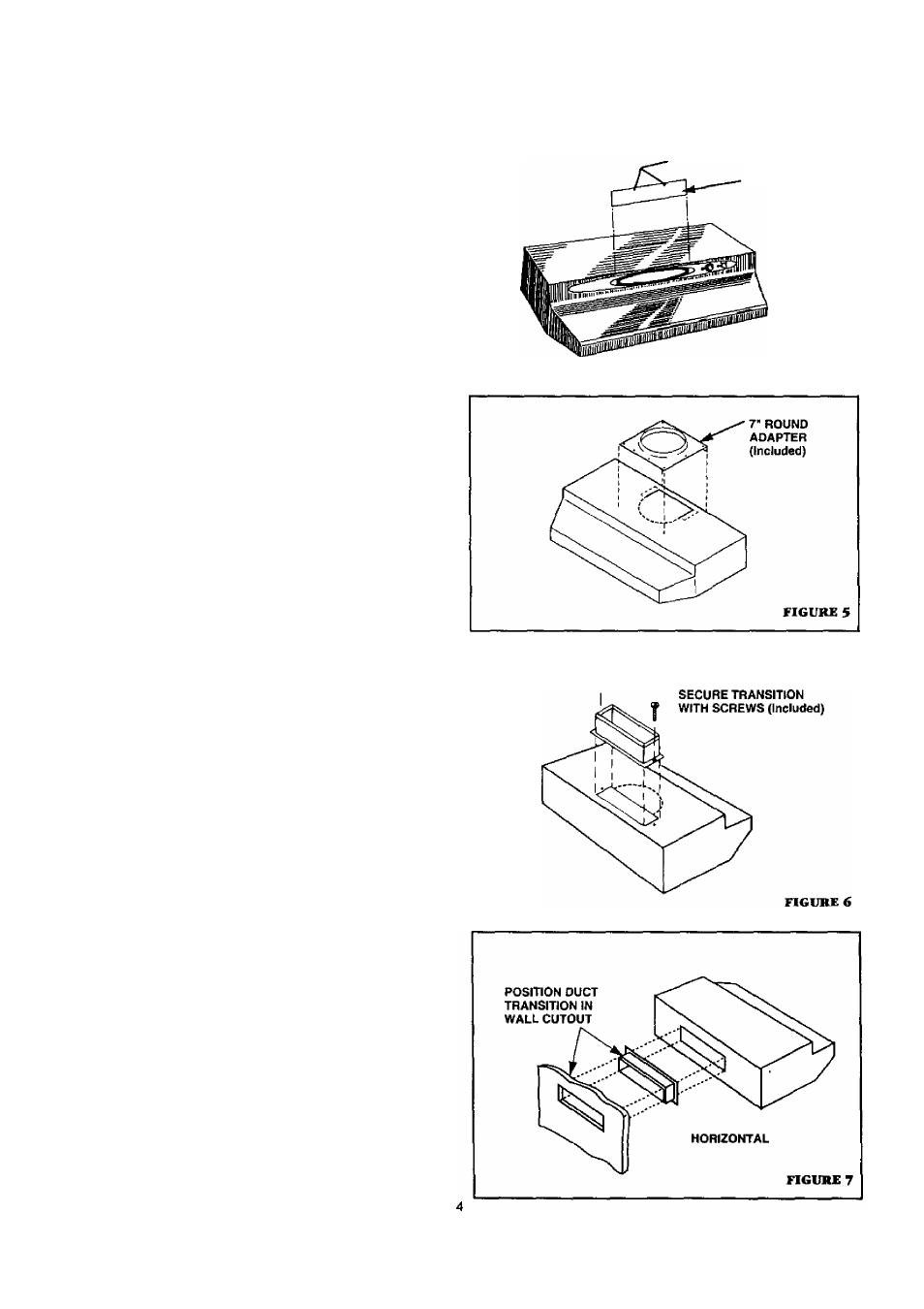
2. For 7" round discharge instaUation, refer to FIGURE 5. Secure
7" adapter (included) to top of hood using screws provided. In
stall 7” round damper (Model BP87, purchased separately).
For 3W” X 10’ vertical discharge installation, refer to FIGURE 6. Se
cure 3W” X 10” transition (if used) to top of hood.
For 3W” X 10” horizontal discharge instaUation, refer to FIG
URE 7. If using the supplied 3W" 10” duct transition, remove the
damper flap from the transition to prevent possible venting inter
ference. Position transition into wall cutout. Note:The transition
does not festen to the hood.
'
3. Feed the wiring through the access hold and into the electrical
box.
4. Align hood’s keyhole mounting slots over the four (4) partially
installed screws.
5. Making sure the duct positions over the hood's duct transition,
push the hood against the rear wall. Secure hood by tightening
screws.
6. Using a long blade screwdriver, reach into the discharge opening
and make sure the damper flap operates freely (vertical discharge
only).
LOCATORS
BAFFLE PLATE
FIGURE 4