Specification chart, Glossary, General information – Sears Craftsman 919.150260 User Manual
Page 5: Description of operation
Attention! The text in this document has been recognized automatically. To view the original document, you can use the "Original mode".
SPECIFICATION CHART
Model No.
919.15026
Horsepower
3/4
SCFM
(w
40 psig
3.0
SCFM @ 90 psig
2.2
Displacement CFM
4.0
Bore
13/4"
Stroke
1
V4"
Voltage-Single Phase
110-120
Minimum Branch Circuit Requirement
15 AMPS
‘Fuse Type
Time Delay
Amperage at Max. Pressure
10
*A circuit breaker is preferred. Use only a fuse or circuit breaker that is the same rating as the branch circuit the air
compressor is operated on. If the air compressor is connected to a circuit protected by fuses, use time delay fuses.
GLOSSARY
SCFM or CFM:
Standard Cubic Feet per Minute; a unit
of measurement of air delivery.
PSIG or PSI:
Pounds per square inch gauge.
U.L. Listed;
Underwriter laboratories; samples of com
pressor outfits, taken from production, were submitted to
U.L. and found to comply with their requirements for
design and performance.
GENERAL INFORMATION
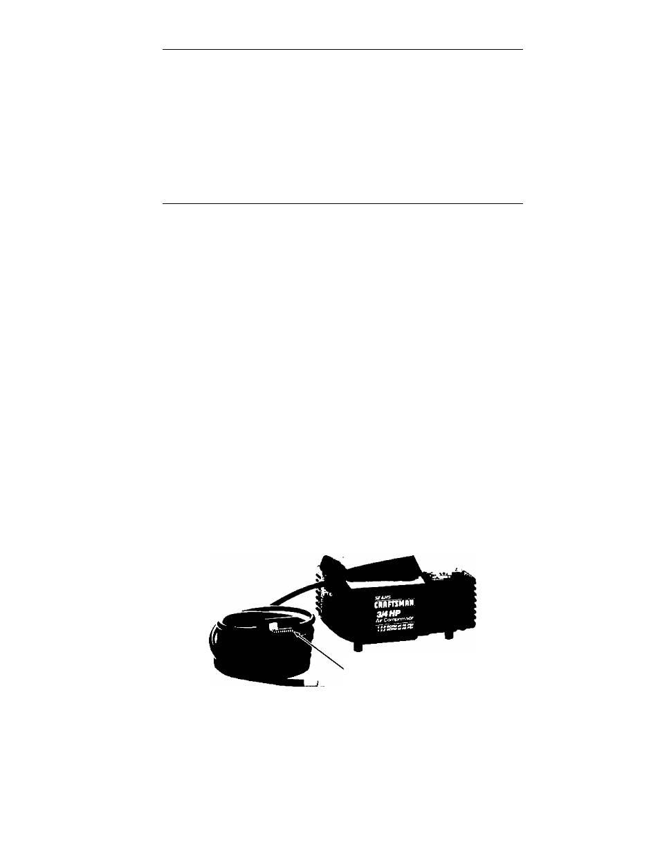
Congratulations! You have purchased a one cylinder,
%
HP compact permanent lube compressor. The absence
of a tank, and ultra light weight gives you added mobility
as well as ease in storage, while the % HP motor allows
you to utilize many air tools, including inflators, blow
guns, spray guns, air brushes, caulking guns and etch
ers. Permanent lube design means you never have to
add oil which also guarantees that you will spray entirely
oil-free air.
A
V
a
X15' air hose with integral pressure adjusting valve
is supplied with your compressor, as well as an air chuck.
Accessories for use with your new compressor are avail
able through the current Sears sales catalog, or at full
line Sears stores. Your compressor will operate many
accessories. Check the pressure and flow rating recom
mended by the accessory manufacturer - be sure it is
compatible with the air delivery of your compressor.
DESCRIPTION OF OPERATION
Valve
AaaamAly
Air Compressor Pump:
To compress air, the piston
moves up and down in the cylinder. On the downstroke,
air is drawn in through the air intake muffler. The exhaust
valve remains closed. On the upstroke of the piston, air is
compressed. The intake valves close and compressed
air is forced out through the exhaust valve and then
through the air hose.
Adjustable Pressure Valve:
The pressure valve con
trols the amount of pressure going from the air compres
sor to the accessory. The pressure adjusting valve can
be used to set pressure between 10 and 100 P.S.I. (100
P.S.I. is the highest pressure this compressor will
deliver.) Always set the pressure valve at or below the
required pressure for the accessory being used. THE
ADJUSTABLE PRESSURE VALVE MUST BE SET AT
“START” BEFORE YOU START THE COMPRESSOR.