A caution – Carrier 58DXC User Manual
Page 3
Attention! The text in this document has been recognized automatically. To view the original document, you can use the "Original mode".
9. Reinstall combustion-air diffuser with vents to front. (See Fig.
3.)
10. Do not reinstall burner enclosure front at this time.
Step 2—Conversion of Gas Valve and Inlet Gas Pressure
Check
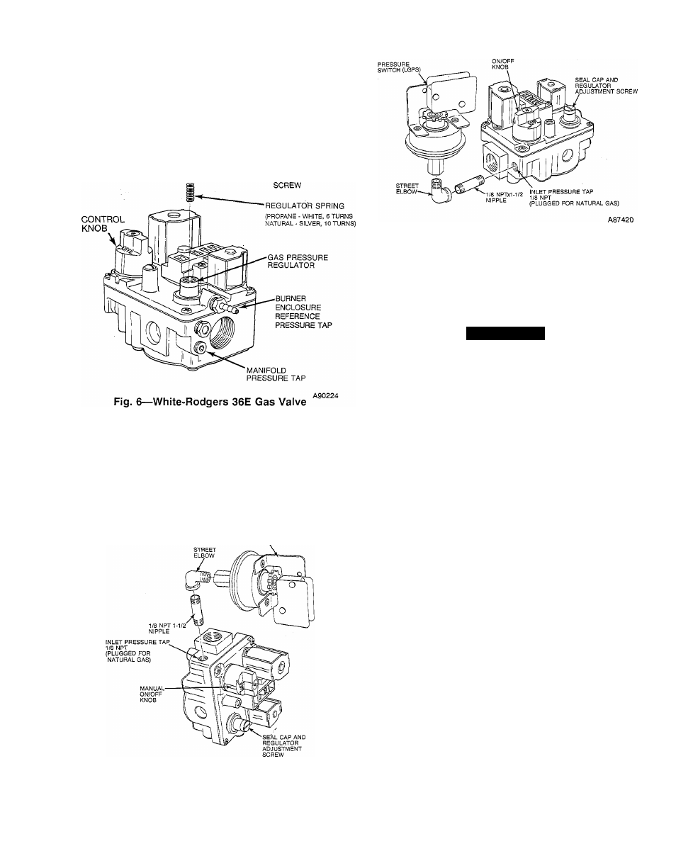
1. Remove regulator seal cap. (See Fig. 6.)
-REGULATOR
SEAL CAP
-REGULATOR
ADJUSTMENT
2. Remove regulator adjustment screw and natural gas regulator
spring (silver).
3. Install white propane regulator spring provided in kit.
4. Replace regulator adjustment screw. Do not reinstall regulator
seal cap at this time.
5. Remove 1/8-in. pipe plug from inlet pressure tap on gas valve.
(See Fig. 7 or 8.)
PRESSURE
SWITCH (LGPS)
A88209
Fig. 7—Installation of Pressure Switch
(Downflow Furnace)
6. Check inlet propane gas pressure as follows:
Fig. 8—Instaliation of Pressure Switch
(Upflow Furnace)
NOTE:
This kit is to be used only when inlet propane gas
pressure is between ll.O-in. wc and 13.6-in. wc.
a. Attach manometer at inlet pressure tap on gas supply side
of furnace gas valve.
A CAUTION
Do not operate furnace more than one minute to check inlet
gas pressure since conversion is not complete at this time.
b. Set room thermostat to “call for heat.”
c. Turn gas supply manual shut-off valve ON.
d. Turn furnace gas valve control knob ON.
e. Turn ON electrical supply to furnace.
f. When burners have ignited, cotifirm proper injet gas
pressure.
g. Turn furnace gas valve control knob OFF.
h. Turn gas supply manual shut-off valve OFF.
i. Turn OFF electrical supply to furnace.
j. Remove manometer.
NOTE:
Use a propane gas resistant pipe dope. Do not use Teflon
tape.
NOTE:
The inlet gas pipe must be disconnected from the valve so
the pressure switch can be installed.
7. Apply pipe dope sparingly to both ends of pipe nipple
(provided in kit) and install nipple in 1/8-in. tapped opening in
gas valve; finger tighten. (See Fig. 7 or 8.)
8. Apply pipe dope sparingly to threaded end of street elbow
(provided in kit). Install elbow on nipple; finger tighten. Use
small pipe wrench for final tightening.
9. On upflow furnaces, point male end of street elbow vertically
up and tilted back to clear control compartment access door.
(See Fig. 8.)
10. On downflow furnaces, point male end of street elbow
towards front of gas valve. (See Fig. 7.)
11. Apply pipe dope sparingly to end of inlet gas pipe and
reconnect pipe to gas valve.
12. Install propane pressure switch (provided in kit) on street
elbow. After switch has been finger tightened, use small
wrench on base of pressure switch for final tightening. When
pressure switch is tight, switch terminals should point toward
right side of furnace.