Step 8, Step 9 – Winco EC22000/A User Manual
Page 19
7
60706-23
224-00
STEP 8
Locate the hose (ref. C) on the left side of the engine that has a plastic ball insert-
ed in the end of it. Use a small screw driver to remove the ball.
Slide green hose clamp (ref. 10) over hose (ref. C) using a pliers.
Route hose assembly (built in step 7) from the carbon canister (ref. 2) to this hose
and insert the connector (ref. B) into hose (ref. C).
Slide green hose clamp down to the end of the hose clamping it to the connector
(ref. B).
•
•
•
•
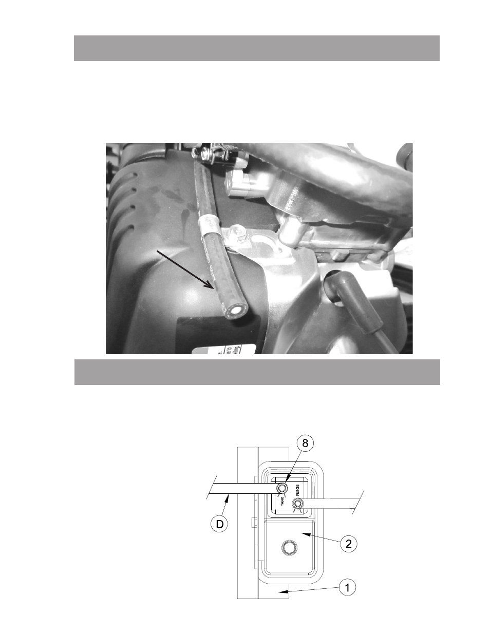
STEP 9
Attach customer supplied 5/16” fuel hose to hose fitting elbow (ref. 11) on top of
the fuel tank. See step 4 for illustration.
Route hose (ref. D) to the carbon canister (ref. 2) and connect to the nipple
marked TANK using black hose clamp (ref. 8).
•
•
C
This manual is related to the following products: