Winco MDS50E3/B User Manual
Page 6
Page 4
c.
“START” - When the switch is rotated to this
position the starter will engage, starting the engine. When
the switch is released, it is spring loaded back to the run
position.
2.
Murphy Switchgauge (2) - The switchgauge will
shut down the engine in case of low oil pressure or high
water temperature. When starting the unit the button on
the switchgauge must be depress as the key switch is
rotated to the start position. It is released after the engine
builds oil pressure.
3.
DC Control Circuit Breaker (DCCB) (3)- The 15
amp DC Circuit Breaker protects the engine control and
the engine ignition circuit against faults in wiring or control
equipment.
4.
Engine Instruments
a.
Oil pressure monitor gauge (OPG) (4)- The oil
pressure gauge is mounted on the front control panel and
indicates the engine oil pressure. The gauge serves a
dual function. In addition to displaying the oil pressure it
also provides the shutdown signal to the switchgauge if
the pressure should drop too low. The shutdown signal is
factory preset at 15 psi (103 kPa/m sq).
b.
Coolant temperature monitor gauge (CTG) (5)-
The coolant temperature gauge indicates engine coolant
temperature. The gauge serves a dual function. In
addition to displaying the water temperature it also
provides the shutdown signal to the switchgauge if the
water temperature gets too high. The shutdown signal is
preset to operate at 225 f (407 k)
c.
Battery Voltage Meter (6)- This DC voltmeter
monitors the VOLTAGE of the battery under static (at
rest) conditions, and under cranking and charging
conditions. The voltmeter indicates not only the condition
of the charging system, but also indicates the battery
reserve under cranking load in cold weather.
d.
Running Time Meter (7)- This DC meter records
the total hours the engine has run.
5.
AC Generator Controls
a.
Voltage adjust rheostat (8)- Controls the output
voltage of the generator by varying voltage regulators
reference voltage.
b.
Field circuit breaker (FCB) (9)- Protects voltage
regulator and exciter field in the event of a load short
circuit or equipment malfunction.
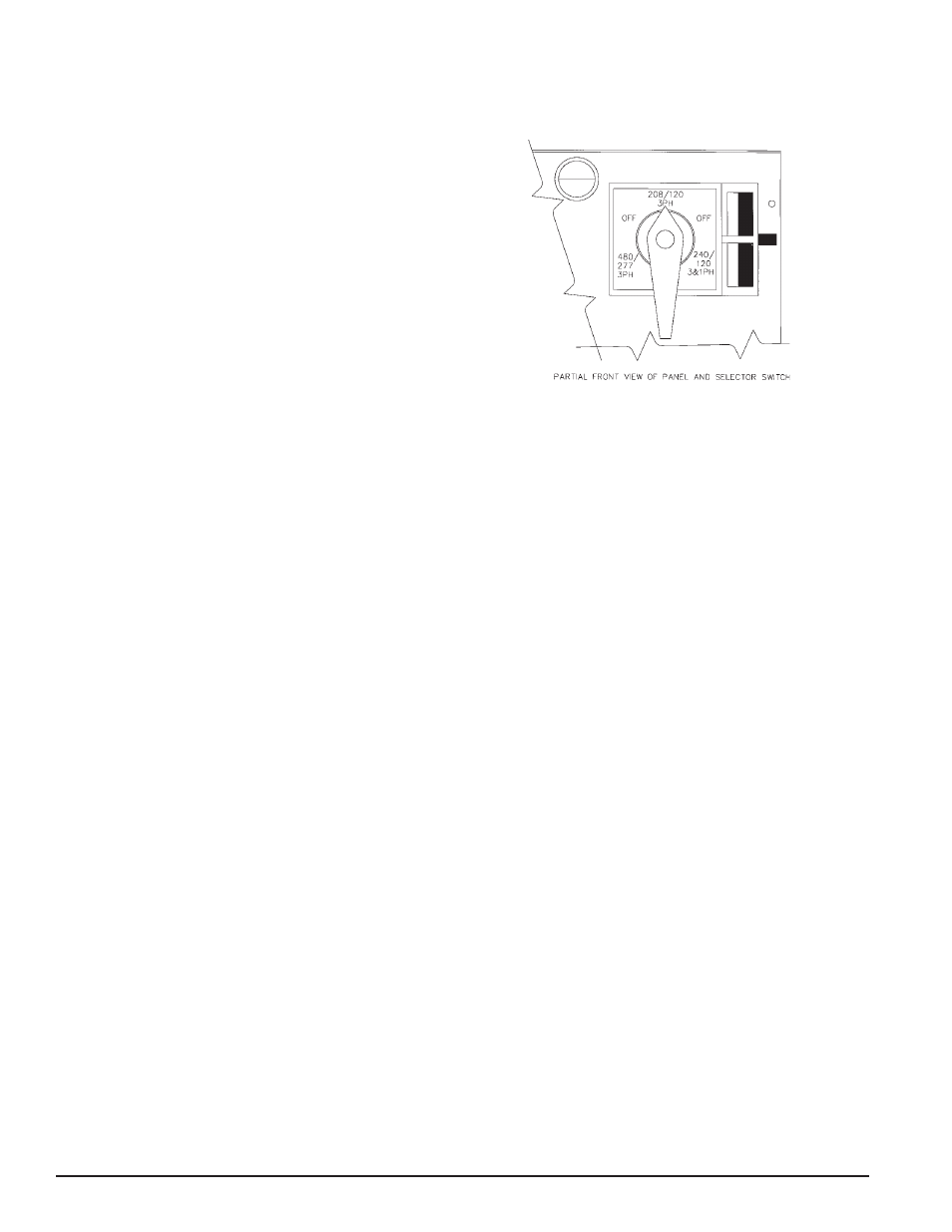
c.
Voltage selector power switch (10)- This heavy
duty three position switch allows the operator to quickly
and safely reconnect the 12 lead generator to any one of
three output voltages. Once the output voltage is se-
lected, the switch may be locked to prevent it from
accidentally being changed during operation. Three
output voltage combinations are available with this
selector switch:
1.
120/240 Three Phase* (series Delta
configuration)
2.
120/208 Three Phase (Low or Parallel “WYE”
configuration)
3.
277/480 Three Phase (High or series “WYE”
configuration)
*This selector position is also used for single phase 120/
240 output by using only the L1 and L2 leads. The three
phase L3 output lead is the “wild” leg in the delta configu-
ration.
6.
AC Generator Instruments
a.
VM/AM Selector Switch (11)- This selector switch
allows you to check the amperage being drawn from
each generator leg and your line to line voltage.
b.
AC Voltmeter (VM) (12)- Monitors generator
output line to line voltage, for all voltage operations.
c.
AC Ammeter (AM) (13)- Monitors the amperage
that is being drawn from each leg of the generator.
d.
AC Frequency Meter (14)- Monitors the generator
frequency.
7.
Panel Light (15) (16) - A panel light is provided for
your convenience. It is activated by the panel light switch.
B. RECEPTACLES and CIRCUIT
BREAKERS
1.
120 Volt 20 Amp Ground Fault Interupter Duplex. This
duplex receptacle is protected by a 20 Amp circuit
breaker mounted just above the duplex. With the “T” slot
design both 15 and 20 amp 120 volt cords can be
plugged in.
2.
120 Volt 20 Amp 3 wire twist lock, NEMA Spec L5-
20. This twistlock receptacle is also protected by a 20