Initial start up – Winco PSS15B2W-18/A User Manual
Page 10
PAGE 8
60706-170
4190-10
If only specific circuits are to be powered under emer-
gency power failure conditions, an additional distribution
panel designated “emergency distribution panel” must be
installed.
All selected emergency circuits are removed from main
distribution panels and reinstalled in the emergency
distribution panel. Suggested circuits: freezer, refrigera-
tor, furnace, emergency lights, sump pump, emergency
outlet circuits, etc. Total running load must not exceed
generator rating.
D.C. ELECTRICAL INTERCONNECTION
*******CAUTION******
Never run the AC and DC wiring in the same conduit.
WINCO NON-UL ATS
Two control wires are required to be installed between
the A.T.S. panel and the generator control terminal box.
Depending on the distance 14 to 16 gauge stranded wire
should be used. These wires will be labeled “Bat -”, and
“Start”.
The control wires will be connected as follows in the
ATS and the generator control terminal box:
ATS Panel
Generator Control Panel
Start 1
to
Wire # S1, (Bat Neg)
Start 23
to
Wire # S23 (Start)
WINCO UL ATS
Your DC connection points in the UL ATS are marked
“X1” and “X2” in the lower right hand corner of the control
board. The wire labeled “S1” is routed to start contact
“X1” and the wire labeled “S23” is routed to start contact
“X2”
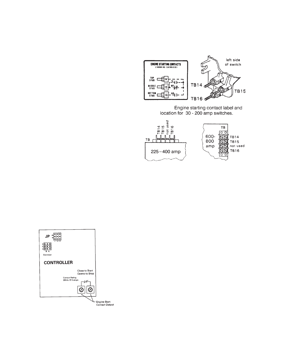
ASCO 300 UL SWITCH
Your DC connection points in the ASCO UL ATS are
terminals “14” and “15” .Depending on the size of the
switch they are located in differnt locations. See below
INITIAL START UP
*************
***** WARNING *****
*************
DO NOT jump start these engine generator sets. Starting
these units on a low battery or jump starting them will
cause damage to the engine control module.
Use the following check list to verify correct installa-
tion before starting the engine:
F
Engine oil.* Check level & fill as required with
proper grade/qty.
F
Unit mounting base properly bolted down.
F
Clearance for service and maintenance on all
sides.
F
Proper fuel line material, and size.
F
All fuel line connections tight.
F
Fuel line protected and a moisture trap installed
(may be required for N.G.).
F
LP/NG pressure O.K. 4-6 Oz. (7-11" WC).
F
Battery connections clean and tight.
F
Battery fully charged.
F
All A.C. and D.C. wiring installed and properly
protected.
* Refer to engine owners manual for proper
levels and type.
After completing the above checklist, the engine-
generator set is ready for the initial start-up test.
X1
X2