Initial start up – Winco PSS15B4W/A User Manual
Page 11
PAGE 9
4141-10
60706-168
INITIAL START UP
*************
***** WARNING *****
*************
DO NOT jump start these engine generator sets. Starting
these units on a low battery or jump starting them will
cause damage to the engine control module.
Use the following check list to verify correct installa-
tion before starting the engine:
F
Engine oil.* Check level & fill as required with
proper grade/qty.
F
Unit mounting base properly bolted down.
F
Clearance for service and maintenance on all
sides.
F
Proper fuel line material, and size.
F
All fuel line connections tight.
F
Fuel line protected and a moisture trap installed
(may be required for N.G.).
F
LP/NG pressure O.K. 4-6 Oz. (7-11" WC).
F
Battery connections clean and tight.
F
Battery fully charged.
F
All A.C. and D.C. wiring installed and properly
protected.
* Refer to engine owners manual for proper
levels and type.
After completing the above checklist, the engine-
generator set is ready for the initial start-up test.
PROCEDURE
Engine Generator Set only
Move the right hand toggle switch from stop to the
normal position the alarm light should go out. Next move
the left hand toggle switch from the off to the run position.
You should hear the fuel solenoid engage at this time.
Next lift the toggle switch to the start position and hold.
The starter should engage and the engine will start. As
soon as the engine starts release the toggle switch and it
will return to the run position. If the engine does not start
after 15 seconds release the switch and let the starter rest
for 15 seconds and reattempt to start. If the unit still will
not start, consult the troubleshooting guide in the back of
this manual.
With the engine running smoothly, check the no load
voltage and frequency at wire G1 and G3 (L2 and L6 in
the ASCO ATS) on the generator terminal block in the
A.T.S. The voltage should be 240 volts plus or minus
nominal. The frequency should be between 61.5 to 62
hertz (Hz). The voltage should also be checked between
the hot terminals (L2 and L6) and the neutral to be certain
of a balanced voltage output and a solid neutral connec-
tion. The voltage should be about one half of the line to
line voltage.
** Notice **
If for any reason during the check out procedure the
voltage and frequency are not correct, move the toggle
switch to the “STOP” position and correct the trouble
before proceeding.
After verifying the voltage and frequency are correct,
move the left hand toggle switch to the off position. The
unit should shut off with no time delay. Move the right
hand toggle switch to the stop position, the alarm light
should now light up.
Transfer Switch & Engine Generator
*************
***** WARNING ****
*************
FIRE DANGER -
The left hand toggle switch (Stop-
Run-Start) must be in the stop position unless you are
starting the generator with this switch. Any time this
switch is in the run position the fuel solenoid is open
and can leak fuel if the engine is not running. This
switch is for test running at the unit only and is not
used for automatic operation.
This procedure checks the electrical operation of
automatic transfer switch. If the actual operation does not
follow this procedure, consult the troubleshooting section
in the transfer switch manual.
1. Move the right hand toggle switch from the stop
position to the normal position, the alam light should
go out. The unit is now ready to be operated from the
Automatic Transfer Switch. Leave the left hand switch
in the off/stop position.
*************
***** WARNING *****
*************
PERSONAL INJURY HAZARD -
Install front cover in
transfer switch before operation. An electrical system
fault could cause a flash and severe personal injury
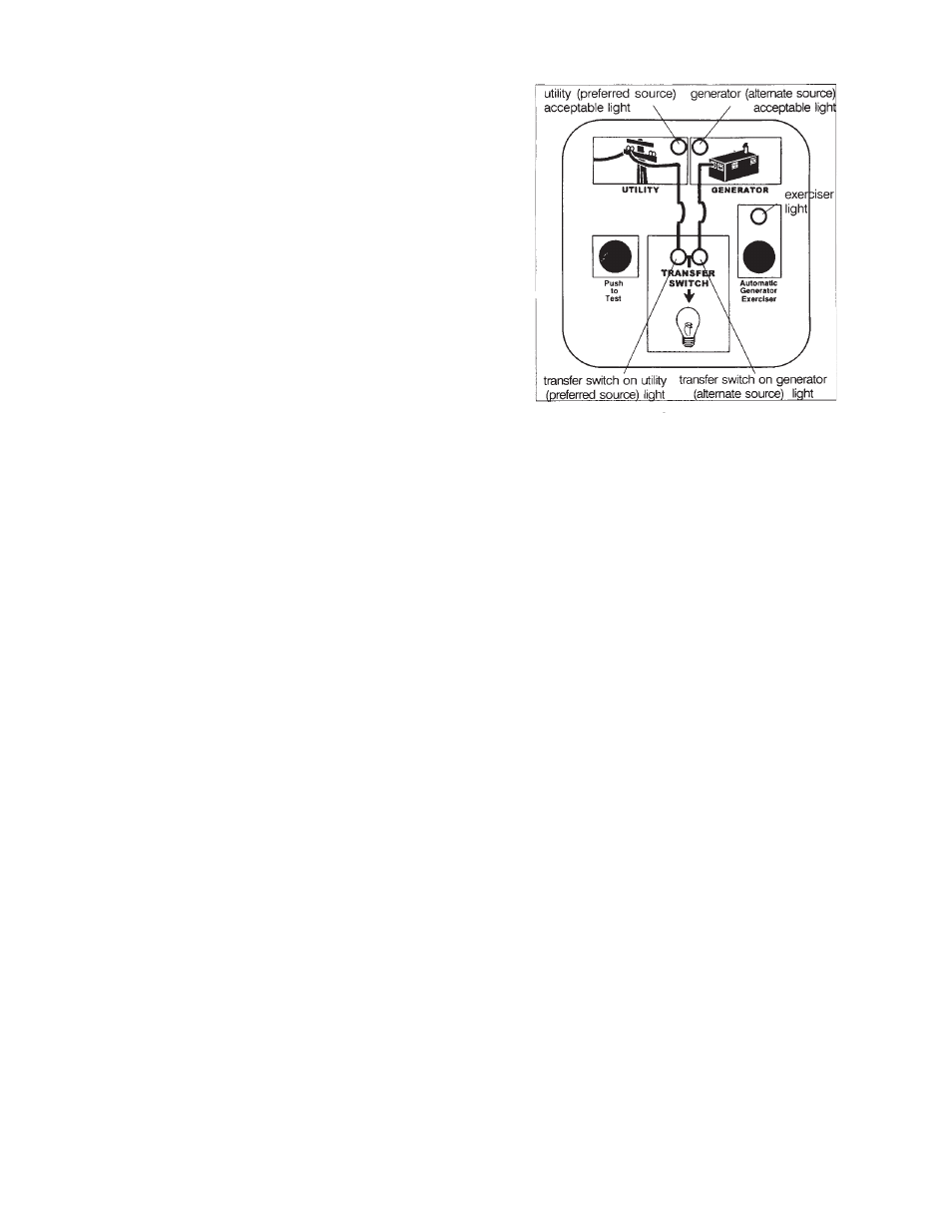
2. Turn on the preferred source (utility) circuit breaker.
The utility source acceptable light should now come on
as well as the transfer switch on utility light. If these
lights fail to come on recheck your incoming power to
insure you 240 volts nominal. If not troubleshoot you
utility source before continuing.