Cabletron Systems 9F120-08 User Manual
Page 24
LANVIEW LEDs
4-2
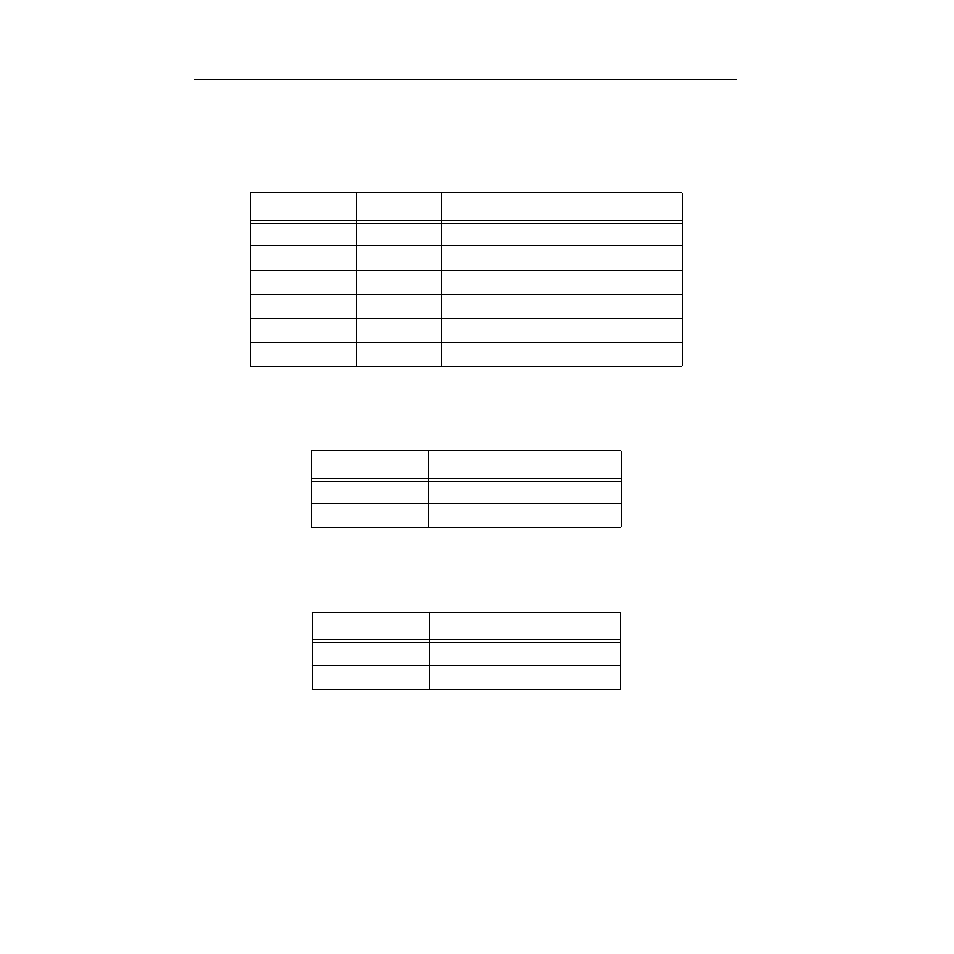
The functions of the System Management Bus (SMB) and the CPU LEDs are listed
in Table 4-1.
The functions of the FNB Receive LEDs are listed in Table 4-2.
The functions of the FNB Transmit LEDs are listed in Table 4-2.
Table 4-1. SMB and CPU LEDs
LED Color
State
Description
Green
Functional
Fully operational.
Yellow
Crippled
Not fully operational (i.e., one bad port).
Yellow/Green
Booting
Blinks yellow and green while booting.
Red
Reset
Normal power-up reset.
Red (Flashing)
Failed
Fatal error has occurred.
Off
Power off
Module powered off.
Table 4-2. FNB Receive LED
LED Color
State
Yellow (Flashing)
Activity
Off
No activity
Table 4-3. FNB Transmit LED
LED Color
State
Green (Flashing)
Activity
Off
No activity
See also other documents in the category Cabletron Systems Computer Accessories:
- 2E42-27R (164 pages)
- 6H122-16 (158 pages)
- 24 (35 pages)
- 9T427-16 (16 pages)
- bridges (132 pages)
- CSX200 (88 pages)
- 2208 (158 pages)
- SM-CSI1076 (69 pages)
- SEHI-22 (93 pages)
- 9T425-16 (40 pages)
- 6000 (180 pages)
- 1800 (448 pages)
- ESX-1380 (86 pages)
- DLE23-MA (202 pages)
- 2E43-51 (168 pages)
- 5000 (83 pages)
- 6H253-13 (62 pages)
- Lancast Media Converter 7000 (108 pages)
- SmartCell 6A000 (102 pages)
- 9G421-02 (12 pages)
- SEH-22 (56 pages)
- 9A000 (180 pages)
- SEH-24 (64 pages)
- 6E123-26 (184 pages)
- STS16-20R (258 pages)
- 2E43-27 (164 pages)
- Cabletron MicroLAN 9E132-15 (36 pages)
- 9E428-36 (18 pages)
- Device Management Module Dec GigaSwitch (65 pages)
- ELS10-26TX (18 pages)
- MICROMMAC-22T (105 pages)
- CSX1200 (644 pages)
- 7H02-06 (36 pages)
- 150 (106 pages)
- 9F206-02 (10 pages)
- MMAC-Plus 9T122-24 (27 pages)
- SEH100TX-22 (52 pages)
- 7C03 MMAC (16 pages)
- 2H253-25R (64 pages)
- TRXI-42 (92 pages)
- 7C04 (150 pages)
- 2H22 (120 pages)
- 2000 (196 pages)
- 7C04 Workgroup (25 pages)