Preparing the unit – Winco HD6010DEX User Manual
Page 7
Page 5
60706-113
WINCO PORTABLE SERIES
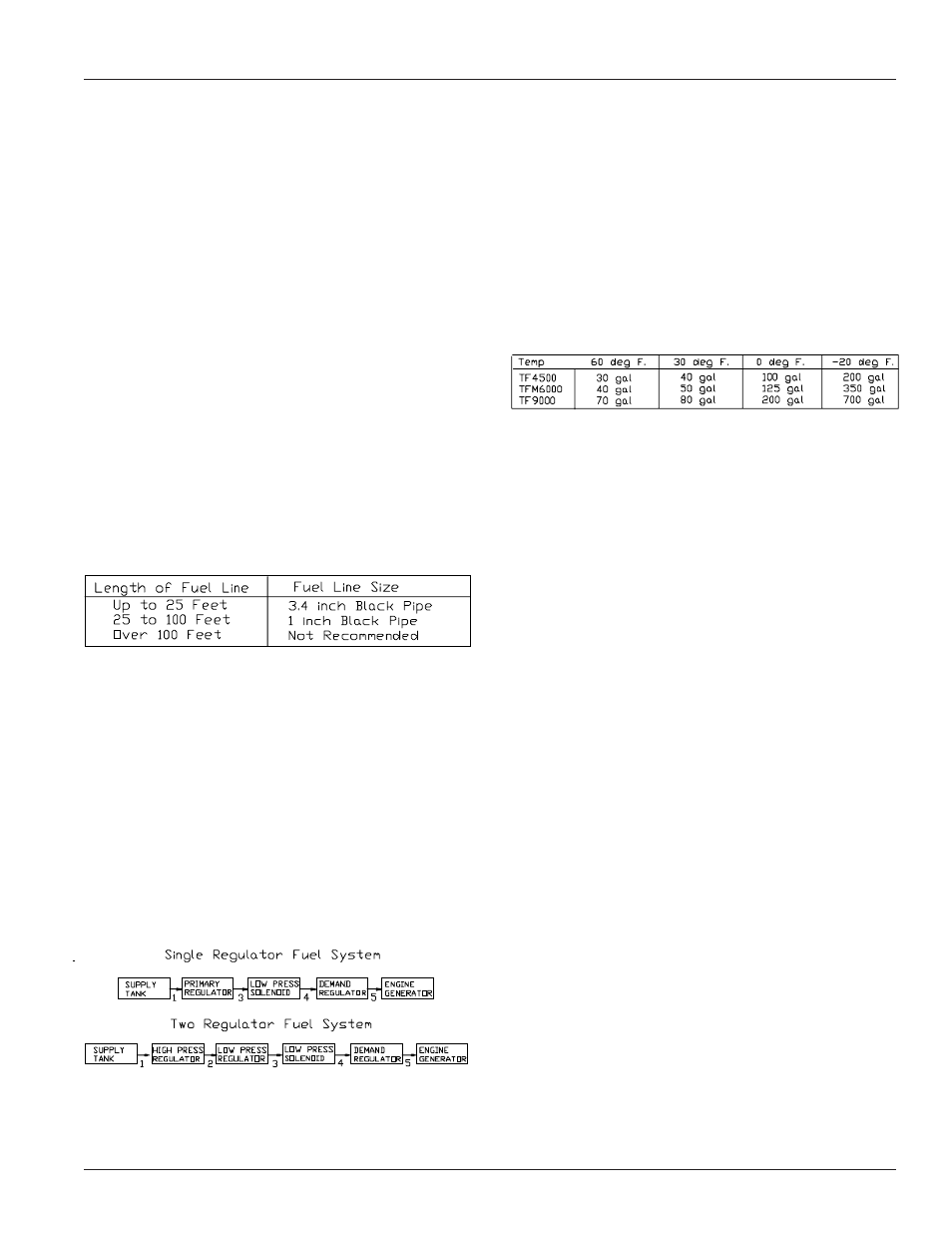
The line size from the table below applies to the distance
from the second regulator to the demand regulator. A
positive fuel shut-off device must be installed in the fuel line
close to the engine generator set. This may be either a
lockable manual shut-off valve available from your local fuel
installer, or a 12 volt DC fuel solenoid valve. This optional
12 volt DC valve is available through your local Winco dealer
as part number 42942-000.
The fuel line used to connect the supply line to the demand
regulator must be a locally approved flexible fuel line.
Products used will vary in different regions depending on
availability and local codes. Consult with your local fuel
supplier to insure complete compliance with ALL codes.
1. Remove the pipe plug from the demand
regulator.
2. Connect the flex fuel line to the demand
regulator.
DANGER: PERSONAL INJURY
Do not use galvanized pipe in the fuel line runs. The
galvanized coating will become eroded and flake off,
causing possible obstruction or damage to the regulator or
fuel valve. The obstruction could cause an inoperative
engine or an explosive fuel leak.
Size of pipe required for generators operating on natural
gas/LP gas.
*allow an additional 3 feet for each standard elbow. Do not
use ‘street ells’ (restrictive)
DANGER! - FIRE - PERSONAL INJURY -
Be careful when sealing gas joints. Excessive sealing
compound can be drawn into the solenoid, regulator or
carburetor causing an engine malfunction or dangerous fuel
leak.
FUEL PRESSURE
Correct fuel pressure cannot be stressed enough. The
most common cause for inoperative systems is an
inadequate or incorrect fuel pressure. Power and
performance of the engine is in direct relation to the
correctness of the fuel system. Shown below is a block
diagram of a typical L.P. or N.G. installation.
Reference numbers 1 through 4 in the block diagrams
above are fuel lines supplied by customer.
Reference number 5 is already installed on your engine
generator set.
Remember that whichever fuel delivery system or type of
vapor fuel used, the fuel pressure at the demand regulator
installed on the engine generator must be between 4 and 6
oz (7-11 inches of water column). Any lower pressure and
the unit will starve for fuel under load. Any higher and the
unit will ‘flood’ when attempting to start.
LP TANK SIZING
Once above the minimum acceptable size, the size of L.P.
tank used will generally depend on how long you want the
unit to run without re-filling. The tank sizes shown below are
the smallest recommended tank sizes based on the outside
temperature. Keep in mind the colder it gets the slower L.P.
will vaporize. This is the reason for the larger tanks at low
temperature. Minimum sizing is not based on running time.
CHANGING FUEL TYPES
These engine generator sets are designed to run on
three different fuels;
gasoline, natural gas or LP vapor.
They may be easily changed from one fuel to another.
FROM GASOLINE TO LP/NG
1.
With the engine running turn off the gasoline
fuel valve.
2.
Run the engine until it runs out of fuel.
3.
Remove the pipe plug from the demand
regulator.
4.
Install locally approved flexible fuel line.
5.
Connect the LP/NG vapor fuel line.
6.
Turn on the vapor fuel.
7.
Start the engine.
8.
Apply the load to the generator.
9.
Adjust the fuel mixture valve to smooth the
engine out.
Note: Operating on LP/NG vapor fuel for an extended period
of time without liquid fuel in the carburetor may damage the
carburetor float, and the needle seat assembly. If you plan
to convert back to gasoline, we recommend the float and
needle seat assembly be removed from the carburetor.
(Consult a local engine supplier for assistance.)
FROM LP/NG TO GASOLINE
1.
With the engine running turn off the LP/NG fuel
supply.
2.
Run the engine until it runs out of fuel.
3.
Remove the flexible fuel line from the demand
regulator.
4.
Reinstall the pipe plug in the regulator. (use
thread sealant sparingly)
5.
Check to be sure the gasoline fuel valve is off.
6.
Fill the gasoline fuel tank.
7.
Turn on the gasoline fuel valve.
8.
Start the engine.
9.
Adjust the load jet on the carburetor as
required to smooth the engine out.
PREPARING THE UNIT