Winco Rotating Armature Design Troubleshooting Guide User Manual
Page 2
60711-020
9089-10
field is grounded and should be repaired or replaced. To
determine which of the fields is grounded, cut the connec
tor between the two coils and retest to determine which
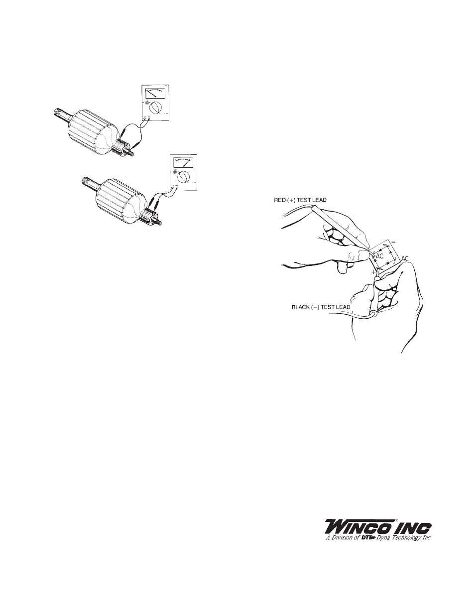
B. Testing the Armature for Opens and Grounds
1. Remove all brushes.
2. Ground fault test - set multimeter to read high resistance
(meg-ohms).Holding one meter lead against a clean spot
on the armature shaft, touch the other lead to each of the
slip rings (one at a time) while observing the meter. If meter
indicates continuity (any reading lower than one meg-
ohm), the armature is grounded. Dirt between the slip rings
and on the insulator surface can cause grounding. If ground-
ing was indicated, carefully clean all dirt off the slip rings and
their insulators and then recheck it. Replace the armature if
it is grounded and unrepairable.
3. Open Test. Set meter to read low resistance (R x 1
ohms). Holding one meter lead on surface of slip ring
No. 1, touch other meter lead to surface of slip ring No.
2 while observing the meter. Meter should indicate
continuity (low resistance - less than one ohm is typical). If
the meter indicates open circuit (infinite resistance) part of
armature winding is open. This may be caused by a
repairable defect in the connection at the slip ring, however
generally an open armature will have to be replaced.
Continue reading the continuity between slip ring No. 2 to
No. 3 and No.2 and No.4. All the slip rings should have
continuity to slip ring number 2, the neutral ring.
NOTE: If these tests have not located the trouble, remove the
armature and have it tested for opens, shorts, and grounds on
a growler.
C. Testing Rectifiers
The field excitation is supplied through a full wave bridge
rectifier. This type of rectifier has four terminals, two AC, a
DC positive and a DC negative.
A rectifier may be tested in the following manner:
1. Disconnect all leads from rectifier.
2. Connect the red ohmmeter lead to the positive DC (+)
terminal.
3. Connect the black lead to each of the AC terminals in turn.
Either a high or low resistance reading will be obtained.
4. Reverse the meter leads, (black lead to the DC POS (+)
and red to the AC terminals, each in turn. An opposite
reading should be observed.
5. Connect the red ohmmeter lead to the negative DC (-)
terminal.
6. Connect the black lead to each of the AC terminals in turn.
Either a high or low resistance reading will be obtained.
7. Reverse the meter leads, (black lead to the DC NEG (-)
and red to the AC terminals, each in turn. An opposite reading
should be observed.
8. Check each terminal to the case. An open circuit (very
high resistance) reading should be observed. A battery pow
ered test light is used. Follow the same procedures described
above. A good diode element will allow current to pass to the
light in the test lamp when the leads are connected in the
forward direction.
9. If the rectifier fails any of the above tests, it should be
considered defective and replaced.
Condenser Testing
Condensers are built into the generator circuit to minimize
radio interference during operation. If a condenser shorts out,
it will also short out the generator output. To determine
whether a condenser is shorted, stop the generator and
disconnect the condenser lead wire from the brush holder.
Using a multimeter on the R x 100 scale, check the resistance
of the condenser. Normal response is a sharp swing of the
meter towards low resistance and then a steady rise towards
high resistance (open circuit). If the capacitor is shorted it will
show as a constant low resistance.
Otherwise, restart the generator without the capacitor connected
to recheck the generator for output. If the generator then
provides power, the condenser was at fault and should be
replaced. (If the generator doesn't provide power, the problem
was not caused by that condenser, reconnect the lead wire).
225 South Cordova Avenue
Le Center, Minnesota 56057
507-357-6821