Assembly – Craftsman 486.24326 User Manual
Page 4
4
ASSEMBLY
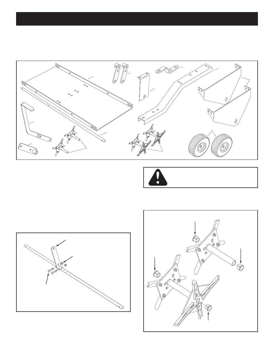
CARTON CONTENTS
1. Tray
2. Wheel Brackets (2)
3. Middle Brace
4. Hitch Bracket
5. Tongue
6. End Plates (2)
7. Lift Handle
8. Lift Lever Assembly
9. Single Spool Assemblies (2)
10. Shaft
11. Double Spool Assemblies (2)
12. Wheels (2)
TOOLS REQUIRED FOR ASSEMBLY
(2) 7/16" wrenches
(2) 1/2" wrenches
(2) 9/16" wrenches
(2) 3/4" wrenches or adjustable wrenches
CAUTION: Points of aerator knives
are sharp! Exercise caution at all times
while assembling and using the aerator.
1
2
3
4
5
6
9
10
11
12
7
8
FIGURE 1
• Attach the lift lever assembly to the two holes in the
middle of the shaft using two 1/4" x 1-3/4" hex bolts
(B) and a 1/4" nylock nuts (K).
Tighten. See figure 1.
• Push split plastic bearings (Y) into both ends of all
single and double spool assemblies. See figure 2.
1/4" x 1-3/4"
HEX BOLT (B)
1/4" NYLOCK
NUT (K)
LIFT LEVER ASSEMBLY
SPLIT
BEARING (Y)
SPLIT
BEARING (Y)
SPLIT
BEARING (Y)
SPLIT
BEARING (Y)
FIGURE 2
- 247.795950 (24 pages)
- 247.797853 (24 pages)
- 315.111450 (12 pages)
- 152.22018 (19 pages)
- 137.21241 (31 pages)
- 572.61096 (59 pages)
- 572.6112 (23 pages)
- 1450 Series Engine (56 pages)
- G8693 (30 pages)
- 247.287751 (27 pages)
- 315.111920 (16 pages)
- 572.610720 (12 pages)
- 247.799891 (21 pages)
- 486.24219 (8 pages)
- 113.213832 (20 pages)
- 987.799601 (44 pages)
- 973.111490 (16 pages)
- 149.236321 (16 pages)
- 973.111330 (16 pages)
- 486.24515 (32 pages)
- 875.19119 (10 pages)
- 316.79246 (20 pages)
- 247.776360 (40 pages)
- 973.111471 (16 pages)
- 247.796890 (20 pages)
- 247.775870 (25 pages)
- 486.243152 (8 pages)
- 486.2454 (8 pages)
- 919.150020 (10 pages)
- 247.77636 (40 pages)
- 320.17217 (20 pages)
- 486.24516 (32 pages)
- 973.111291 (16 pages)
- 973.2748.70 (16 pages)
- 315.111640 (12 pages)
- 315.11516 (4 pages)
- C944.511573 (10 pages)
- 486.243361 (8 pages)
- 486.24218 (12 pages)
- 315.115510 (18 pages)
- 247.795940 (36 pages)
- 486.24336 (8 pages)
- 172.26729 (13 pages)
- 247.795861 (16 pages)