Traxxas 53097-1 User Manual
Page 36
36 • REVO 3.3
BASIC TUNING ADJUSTMENTS
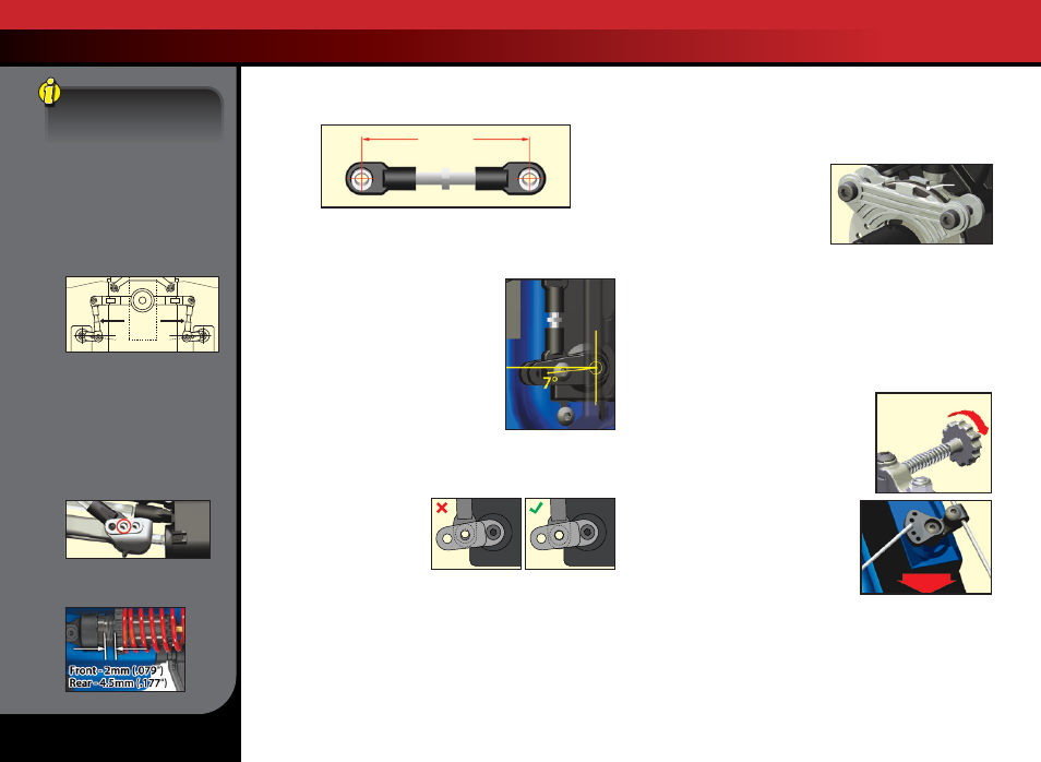
2. Adjust both the steering links to be the exact same length (41.8mm -
use “Steering Link Length Template” below to set length).
3. Switch on the power to the receiver and the transmitter.
4. Adjust the steering trim on the transmitter to the neutral “0” position.
5. Connect one end of a steering link to the steering servo saver arm
and the other end to the servo horn.
6. Position the steering servo saver arm
perpendicular to the centerline
of the vehicle.
7. While holding the steering servo saver arm
in the position mentioned in step 6, install
the servo horn onto the servo so that the
steering link is parallel with the centerline
of the vehicle. This will automatically set the
servo horn at the 7-degree offset shown in
the illustration.
8. Install the second servo horn on the other
side following the same procedure.
9. Fine-tune the length of the second steering link to eliminate any
load on the steering system in the neutral position. Remove one
steering link screw from
the servo horn. Adjust the
steering link until the hole in
the servo horn and hollow
ball line up then reinstall the
screw (see illustration).
If you are using aftermarket servos, it is important to use servo horns
designed for Revo. Optional steering servo horns are sold separately for
use with non-Traxxas servos.
Servo Saver Tuning
An optional stiffer spring is available for the servo saver when using
servos with metal gear sets (see parts list for details). Do not use this
spring with standard Traxxas high-torque servos.
BRAKE SETUP & ADJUSTMENT
Revo is equipped with a disc brake that rides on the yoke of the
transmission’s front output shaft. The brake is preset at the factory
and should not require attention. As the brake material wears, future
adjustments may be necessary.
Brake Shoulder Screw Adjustment
The two shoulder bolts that secure
the brake pads to the transmission
housing may need to be adjusted
periodically as the brake material
wears down. They should be
tightened so a 0.50mm (.020”) gap exists between the disk and the brake
pad (on the transmission side). Adjust in one of the following ways:
1. Use a 0.50mm feeler gauge between the brake pad insert and brake disk.
2. Push the outer brake pad firmly against the inner pad with your
finger, sandwiching the brake disk between the brake calipers.
Tighten the brake shoulder bolts until they just barely touch the
brake pads. Do not over tighten these fasteners or you could damage
the brake calipers. Loosen each of the shoulder bolts by 1 turn.
Brake Linkage Adjustment
When correctly adjusted, the brake linkage
spring should barely touch the rod guide when
the servo is in the neutral position (closed
throttle). This will ensure no brake drag
during operation of the vehicle. The brake
adjustment knob can be threaded away from
the spring for less braking power if desired.
Do not adjust the knob to apply pressure
against the spring while the servo is in the
neutral position. This will induce brake drag
and cause undesirable handling.
The position of the z-bend from the factory
is in the middle position of the servo horn.
Changing this position will affect the way the brake force is applied. The
brake adjustment knob will need to be readjusted if this position is changed.
Brake Pad Wear and Replacement
During normal use the brake pads should wear at a relatively slow rate.
However, if the brake pads wear down close to the metal pad holders,
they should be replaced. Any more wear than this could cause damage
to the brake parts and improper operation of the brake system.
0.5mm
gap
Front of Truck
Less Brake
Brake
Linkage
Spring
Steering Link Length Template
41.8 mm
Increasing Steering Travel
The Revo has the ability
to increase the “throw” of
the steering system and
maximize steering travel. To
increase the steering travel,
move the steering linkages
to the outer holes of the
servo horns. Readjust the
length of steering linkage to
compensate for the servo horn
position change so the servo
horn is at a 7-degree offset.
The maximum travel setting will
cause the steering to be more
sensitive and can increase the
chance of rollover with the stock
suspension setup. The following
steps are recommended to
improve steering stability:
1. Move the push rod to the center
hole of the lower suspension arm’s
push rod mount.
2. Lower the shock preload to 2mm
on the front shocks and 4.5 mm on
the rear shocks.
Linkages
7°
7°