Traxxas 41094-1 User Manual
Page 14
14
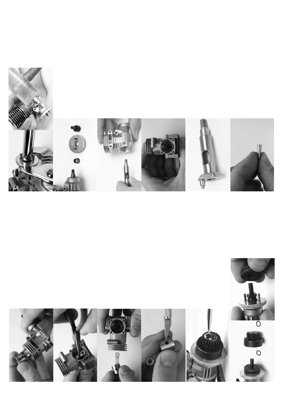
STEP
15:
Remove the connecting
rod and piston through the top
of the crankcase.
STEP
16:
To remove the connecting rod from the piston, use a s
har
p-
point
ed t
ool t
o r
em
ov
e t
he s
mall m
et
al
G-clip in the side of
the piston. Do not re-use the old
G-clip. When installing
a new conne
cting rod, use the
supplied
new G-clip.
STEP
21:
Remove the crankshaft by pulling
it straight out of the
crankcase.
STEP
22:
The bearings are press-fit into the crankcase. To remove them, the crankcase
must be heated
with a
heat
gun or torch. The crankcase
will
expand
with
heat and release
the bearings.
To avoid the possibility
of
burns or other damage, do not attempt
to
remove
the bearin
gs. Clea
n the bearings
by flushing
them
with dena
tured alcohol and then place one or two
drops of after-run oil on the races.
STEP
23:
Before
installing
a
new
connecting
rod,
you
can
increase connecting rod life by
polish
ing the
crankshaft
journal. Use 1200 grit sandpaper to remove the
surface scratches followed
by liqui
d metal polish
to
buff the crankshaft journal
to a bright, smooth shine.
Rinse
thoroughly
with denatured
alcohol.
Lube
with
after-run oil.
STEP
24:
Use the 1200 grit sandpaper
and
the liquid metal
polish
on the wrist pin
also. Rinse
thoroughly
with
denatured alcohol
and lube with after-run oil.
STEP
13:
Pull the sleeve straight up and out of
the crankcase. If
the sleeve will not move, rotate the crankshaft until the sleeve pushes up.
STEP
14:
Rotate the crankshaft
to
bottom dead center. Lightly
grab the
connectin
g
rod with a
pair of
needlenose
pliers and gently pull it off
of the crankshaft journal.
Removing the clutch and
flywheel
STEP
17:
It is not necessar
y to remove
the clutch assembly
unless
you are
servicing
the clutch, crankshaft, or
engine
bearings. Use the tip of a small screwdriver
to
remove the E-clip that holds the clutch bell gear.
STEP
18:
Remove
the clutch bell
gear
and the clutch shoes.
Note that there are two 5x8mm PTFE washers,
one
on each side of the clutch bell
gear. Check the clutch
shoes for
excessive wear
or
cracking around
the
pin
holes. If
the
clutch
shoes
are worn
to
the point that
the clutch
spring contacts
the
clut
ch
bell,
then
the
shoes must
be replaced.
STEP
19:
Grip the flywheel with a
pair of
pliers (locking pliers
work best). Remove the
clutch adapter nut with a 10mm
deep
socket.
Hold
the engin
e
just above your
workbench and tap the
flywheel from behi
nd with a
non-marring
hammer (plastic or wood). Several easy
blows
may be necessary to release
the flywheel
and
split beveled cone.
STEP
20:
The flywheel
and
the split-beveled
cone should pull
smoothly
off
of the crankshaft.