General description, Features, Handling precautions – Toa WM-2110 User Manual
Page 2: Nomenclature, Individual switch settings, Rear] [top] [side] [bottom, Front, Remote control switch, Accessory
2. GENERAL DESCRIPTION
TOA's WM-2110 is a Desk-top Transmitter designed to use 470 MHz band radio signals.
3. FEATURES
• The remote control function permits the unit's transmission to be controlled from external equipment.
• Input sensitivity can be switched between MIC and LINE signal levels depending on the type of equipment to
be connected to the input.
• A maximum of 5 different channels can be simultaneously used in the same location.
• Compact size and high reliability.
4. HANDLING PRECAUTIONS
• Take care not to drop the unit onto the floor nor bump it against a hard object as the unit could fail.
• To clean, wipe with a dry cloth. When the unit gets very dirty, use a cloth damped in a neutral cleanser.
Never use benzene, thinner or chemically-treated cleaning cloth because such volatile liquids could deform
or discolor the unit.
• Keep the unit as far away as possible from a fluorescent lamp, digital equipment, PC or other equipment
which generate high frequency noise.
• To ensure correct signal transmission, do not place metal objects or other impediments which block radio
wave travel around the unit.
• Be sure to install the antenna vertically as doing otherwise may result in transmission failures.
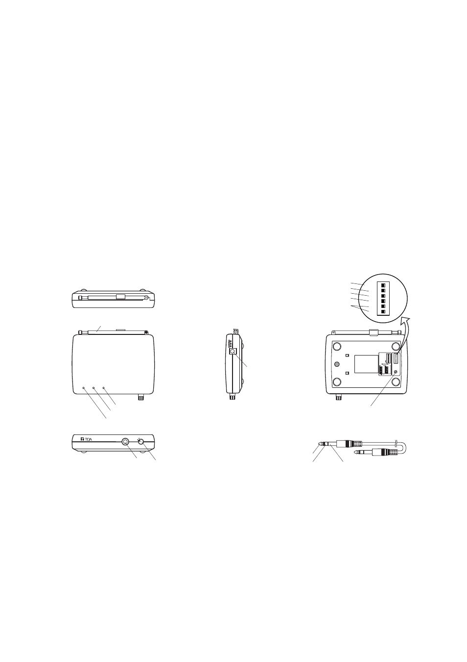
5. NOMENCLATURE
Antenna
Audio signal peak indicator
Power indicator
Channel selector switch
3-pole phone plug cord
Transmission indicator
DC inlet
Input
Audio input
Remote
GND
Power switch
POWER
TX
INPUT
OFF
ON
PWR
AF PEAK
[Rear]
[Top]
[Side]
[Bottom]
[Accessory]
[Front]
WM-2110
MIC/LINE
INPUT
SENS.
MIC
SW position
–66
–60
–54
–24
–18
1
2
3
4
5
–12
LINE
Channel
–
–
REMOTE
M
0
0
–
–
OFF
L
-6
-6
–
–
ON
M
0
0
–
–
OFF
L
–6
–6
–
–
ON
REMOTE
MIC/LINE
INPUT SENSITIVITY
–
–
[About the indicators]
Power indicator (green) :
Lights when the Power switch is set to the ON position.
Transmission indicator (yellow) :
Lights when a radio signal is transmitted.
Audio signal peak indicator (red) : Lights when the signal level from the input terminal is extremely high.
6. INDIVIDUAL SWITCH SETTINGS
6.1. Remote Control Switch
• Setting the Remote control switch to the OFF position places the unit in the transmission mode. No remote
control can be performed. (Note: The remote control refers to the function which permits connected external
equipment to remotely control the unit's signal transmission.)
• To remotely control the unit's signal transmission from external equipment using the remote control input, set
the Remote control switch to the ON position. A radio signal is transmitted when the remote control input
from the external equipment is turned on (i.e. when a 3-pole phone plug's remote control input terminal is at
make with the ground terminal).