Wiring – Toa N-8033MS User Manual
Page 3
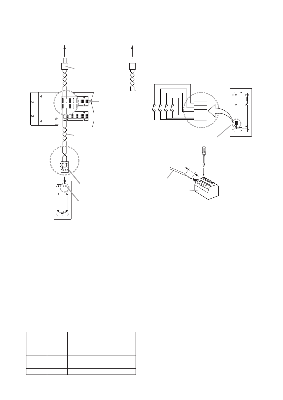
Removable terminal plug (2P)
(accessory)
Line connection terminals
N-8033MS rear
2 1
1 2
E-7000TB
Terminal board
Mini-clamp connector *
(Supplied with the
N-8000EX/8010EX)
Twisted pair cable
N-8000EX/8010EX Exchange
16 lines
Both upper and lower
terminals (clip terminals)
are internally connected.
4. WirinG
4.1. Connection to the exchange
To connect the cables from the N-8000EX/8010EX
Exchange to the N-8033MS, use the removable terminal
plug (2P) supplied with the N-8033MS.
The cables have no polarity.
* There are two types of Mini-clamp connectors, either of
which is supplied with the N-8000EX/N-8010EX.
For details, refer to the next page.
4.4. the type of Cables
The types of cables are to be determined according to the
following conditions.
• Twisted pair wires (such as those used for electronic
push-button telephone) are to be used for wiring
between the Exchange and the stations in principle.
• The number of cables pairs laid should be determined
considering the possibility of future expansion of the
system.
• Outdoor wires should be used where wiring passes
through inaccessible areas such as ceilings or under
floors where the maintenance is not performed. Indoor
wires may also be used, however, in case where there is
no risk of deterioration due to exposure to heat, etc.
note
Specifications related to each junction are as follows.
Mini-clamp connector (N-8000EX/8010EX line terminal)
Conductor diameter: ø 0.4 – 0.65 mm (AWG22 – 26),
Solid wire
Outside diameter: ø 1.05 mm or below
Clip terminal (E-7000TB)
Conductor diameter: ø 0.4 – 0.8 mm (AWG20 – 26),
Solid wire
Outside diameter: ø 1.5 mm or below
Removable terminal plug (N-8033MS line terminal)
Conductor diameter: ø 0.4 – 1.6 mm (AWG14 – 26),
Solid wire/Stranded wire
External dial input terminal (N-8033MS)
Conductor diameter: ø 0.8 – 1.3 mm (AWG16 – 20),
Solid wire/Stranded wire
Conductor
Loop
Maximum cable length
diameter resistance between the Exchange and station.
(mm)
(Ω/ km) (Assuming that the loop resistance is 170 Ω.)
ø0.4
295
570 m
ø0.5
187
900 m
ø0.65
113
1.5 km
ø0.9
58
2.9 km
4.2. relations Between Core Diameter of Cable
and Maximum Cable length
Refer to the following chart as guidelines when designing
the distance between the Exchange and stations so that
loop resistance value becomes 170 Ω or less.
4.3. Connection to external switch
External switches such as footswitches can be connected
to the N-8033MS's external dial input terminals.
Terning on each switch connected to the terminal [7], [8],
[9], or [C] permits the same operation as performed by
pressing the dial [7], [8], [9], or [C].
An electrical current of 1 mA flows through each contact.
note
The cable length from the external switch should not
exceed 3 m.
COM
C
9
8
7
N-8033MS rear
7
8
9
C
COM
External dial input terminals
[Connections]
Press down.
Cable
External dial input
terminal block
8 mm