Wiring, Connection diagram – Toa N-8000CO User Manual
Page 12
12
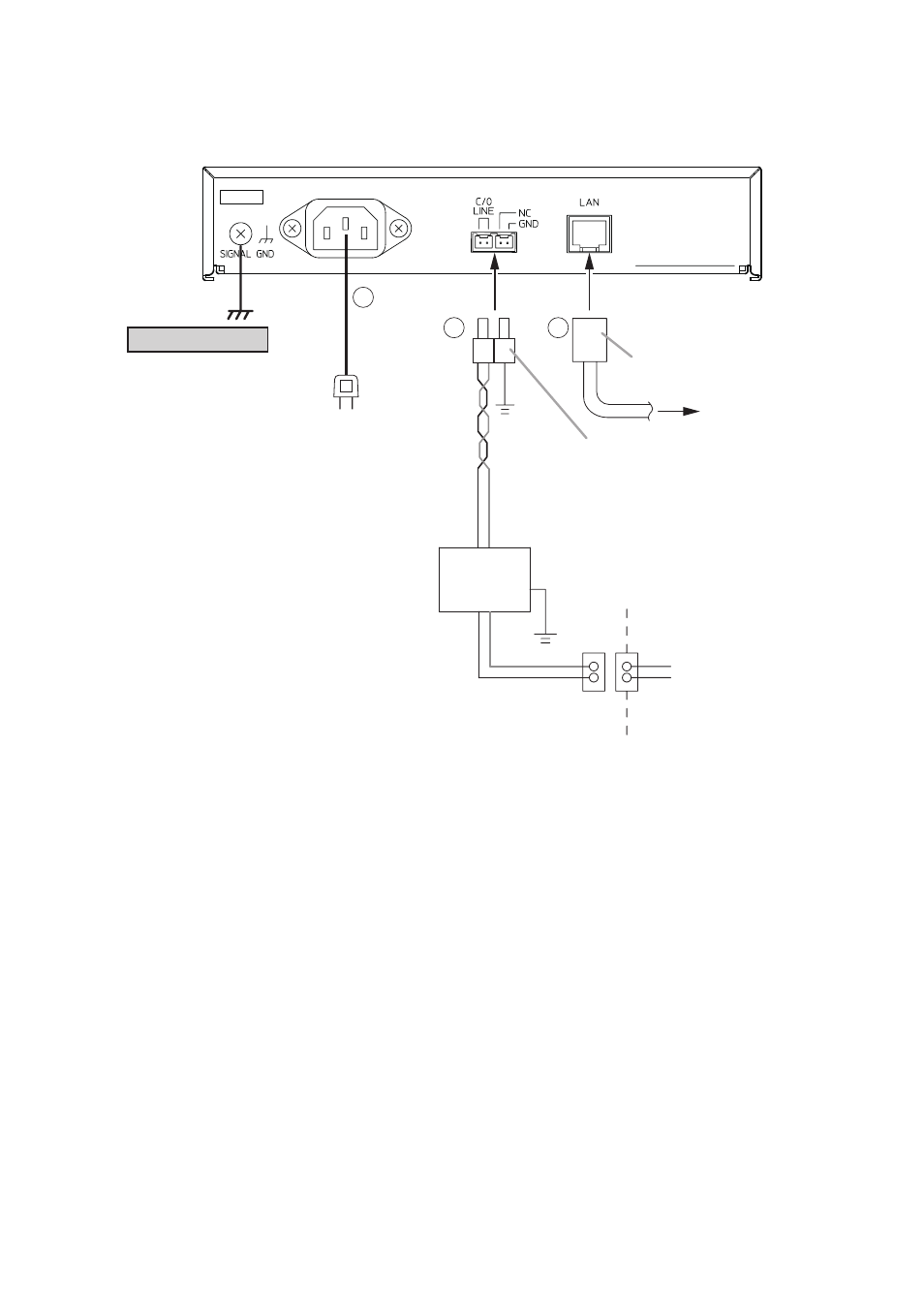
6. WIRING
6.1. Connection Diagram
Be sure to ground.
To AC mains or a UPS
(Uninterruptible power supply system)*
1
Note
If there is a danger of lightning strikes,
insert an appropriate surge arrester
into the power line.
RJ-45 connector
To network
A pair of twisted paid cables
U.S.O.C*
RJ11C or W
Protector *
2
3
Central office line
(or PBX extension)
Mini-clamp connector
232D-02S1B-DA5 (DDK)
(supplied with the N-8000CO)
1
2
3
N-8000CO C/O interface unit
Note
The Interface Unit’s DC resistance is 352 Ω
(maximum).
Depending on line resistance conditions, the
unit might not be usable.
*
1
Select an appropriate UPS taking into consideration the total power consumption of all system
components and the required backup time, and also the requirement that the UPS should employ the
on-line power system.
*
2
Install the protector if the telephone company has not already installed it.
*
3
This terminal is installed by the telephone company.
Reference
C/O interface unit: 6 W (rated) for CE version, 6 W (rated) for CU version
8-Port 10M/100M Switching Hub: 10 W (Differs depending on products.)