Dimensional diagram, Detaching the speaker – Toa BS-1034EN User Manual
Page 4
4
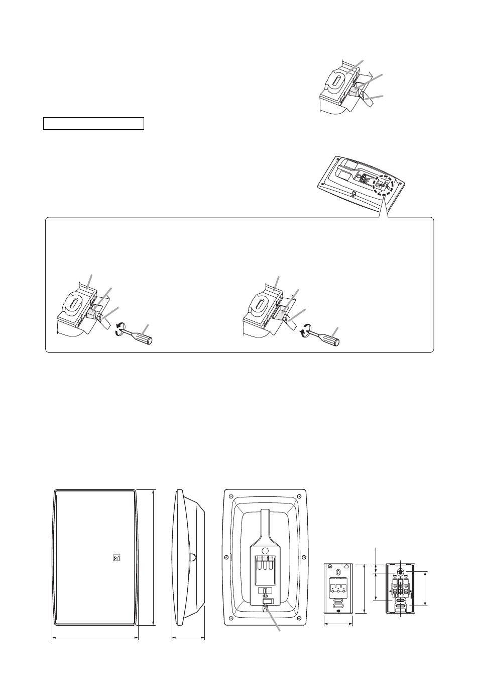
• Speaker receptacle
[Front]
[Rear]
[Front]
[Rear]
[Side]
210 (8.27)
80 (3.15)
70 (2.76)
Lock screw
330 (12.99)
120 (4.72)
83.5 (3.29)
66.7
(2.63)
22.3
(0.88)
6. DIMENSIONAL DIAGRAM
Unit: mm (in)
5. DETACHING THE SPEAKER
Step 1. Turn the lock screw about 3 clockwise turns.
The flap lies down and stays laid. (Refer to "About lock mechanism" explained above.)
Step 2. Hold and slide the speaker to unplug it from the speaker receptacle.
Step 4. Secure the speaker.
Turning the lock screw about 3 counterclockwise turns using
a Phillips screwdriver causes the flap to rise up and stay
upright.
Caution
After speaker installation, be sure to make a visual check that
the flap rises to lock the speaker completely.
Lock screw
Speaker receptacle
Flap
[When fixing the speaker]
[When detaching the speaker]
Lock screw
Phillips screwdriver
Speaker receptacle
Flap
Lock screw
Phillips screwdriver
Speaker receptacle
Flap
Turning the lock screw counterclockwise
causes the flap to rise up and move until it
stops against the other side of the recess.
Turning the lock screw clockwise causes the flap to
lie down and move until it stops against the front
side of the recess. (Factory-preset position)
Shown below is how the lock mechanism works.
It prevents the speaker from being detached easily after installation.
Note
Be sure to follow the instructions below. Failure to do so may cause
damage to the lock mechanism.
· Do not use an electric screwdriver when turning the lock screw.
· Do not turn the lock screw more than the specified turns.
About lock mechanism