Warning – Toa AT-603AP User Manual
Page 3
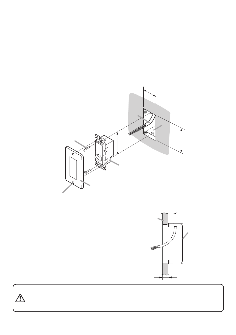
5. InsTALLATIon
Step 1. Install the electrical box into the wall.
Step 2. Make a hole in the wall to mount the unit, then pull out the cables from the wall.
Step 3. Connect the cables to the unit’s terminal block.
note: For details, see “Connection” on the next page.
Step 4. Mount the unit in the electrical box using the 2 supplied screws.
Step 5. Attach the plate (supplied) to the Attenuator.
note: When using the supplied screws to install the unit
to the electrical box, the distance between the wall
surface and the electrical box’s surface should be
less than 27 mm (1.06") as shown below.
Take care not to pinch the lead-in cables when mounting the unit
particularly in a shallow wall-mount box (37 mm or 1.46" deep ). Do
not press the cables into the shallow box by force, as doing so may
damage the unit, resulting in fire or electric shock.
WArnInG
95 − 103 mm
(3.74" − 4.06")
51 − 59 mm
(2.01" − 2.32")
Machine screw M4 x 35
(Accessory)
Machine screw M3.5 x 5
(Accessory)
Plate (Accessory)
Attenuator
Wall
Cable
83.5 mm (3.29")
2
1
3
5
4
Max. 27 mm (1.06")
Wall
A recessed
electrical box