Installation, Continued – Desa Tech S26NTA User Manual
Page 13
www.desatech.com
110361-01F
13
INSTALLATION
Continued
Figure 16 - Removing Blower Brackets
from Stove and Attaching to Blower
Blower
Blower Bracket
Firebox
Top
12. Using the four screws previously removed,
mount blower assembly to stove by reat-
taching blower brackets to rear panel (see
Figure 16). Tighten screws securely.
13. Install plastic control knob onto output shaft of
speed control housing (see Figure 17). Place
speed control housing just inside control com-
partment door in front of stove (see Figure 17).
14. Using two screws provided in blower kit,
mount blower speed control housing to mount-
ing tab in left side of lower control compart-
ment (see Figure 18).
15. Check to make sure that the power cord is
completely clear of blower wheel and there
are no foreign objects in blower wheel.
16. Carefully replace stove top panel. Align holes
and replace six screws removed in step 1,
page 12.
17. Peel off the backing paper and stick the sup-
plied wiring diagram decal on the stove floor
as shown in Figure 18.
18. Plug power cord into a convenient 3-prong
grounded wall receptacle near the stove.
WARNING: Electrical Ground-
ing Instructions: This appliance
is equipped with a three-prong
(grounding) plug for your protec-
tion against shock hazard and
should be plugged directly into
a properly grounded three-prong
receptacle.
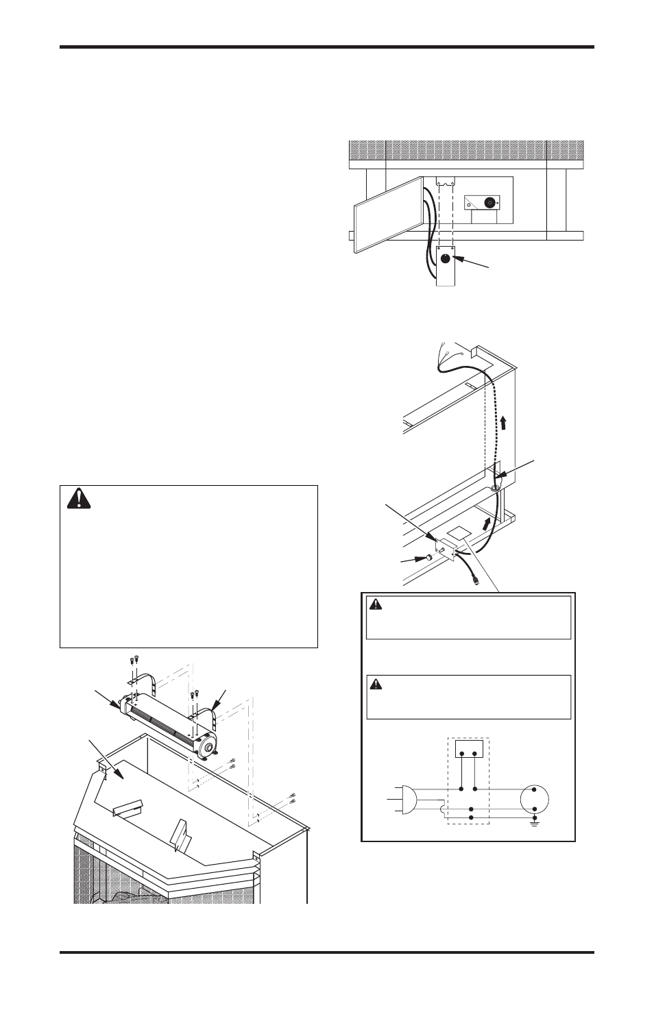
Figure 17 - Installing Blower Control
Housing
Power
Cord
Speed
Control
Housing
Control
Knob
Figure 18 - Routing Power Cord
Blower Speed
Control Housing
Wiring Diagram Decal
Variable
Fan Switch
White
White
Black
Green
On
110/115
V.A.C.
Blower
Motor
Black
Black
Black
Off
120 Vac.
60 Hz. .
78 Amps
WARNING: Never attempt to service heater while it
is plugged in, operating or hot. Burns and electrical
shock could result. Only a qualified service person
should service or repair heater.
If any of the original wire as supplied with the appliance
must be replaced, it must be replaced with 105°C wire or
itʼs equivalent.
WARNING: Label all wires prior to disconnec-
tion when servicing controls. Wiring errors can
cause improper and dangerous operation. Verify
proper operation after servicing.
DESA Heating Products, Bowling Green, KY
19. Using speed control knob, turn blower on and
check for operation.
20. All remaining parts from blower kit may be
discarded.