Installation and instructions, Vfbc wiring diagram - all sizes – Sure Heat VFBC Firebox User Manual
Page 13
Installation and Instructions
13
Electrical Junction Box
Wiring should be connected at a customer
provided junction box, outside the firebox, prior to the
installation of the blower kit.
Electrical Services
If an electrical supply of 120V is being roughed in
to the fireplace junction box to provide for future
installation of the optional blower kit, the wiring should
be connected to the junction box.
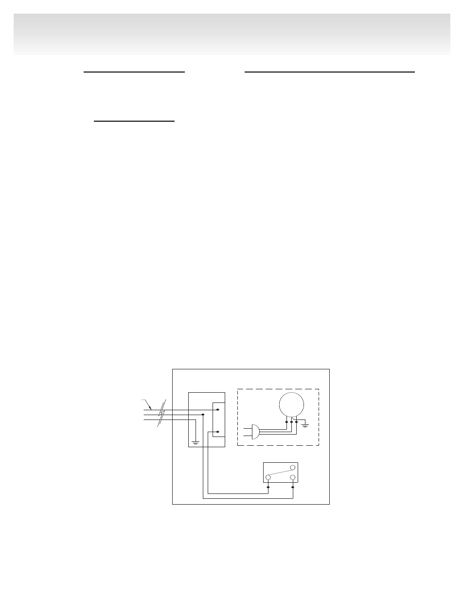
NOTE: All electrical connections (Fig. 12) are to
be made in accordance with CSA Standard C22.1
Canadian Electrical Code part 1 or with the National
Electrical Code, ANSI/NFPA 70 (latest edition) and/or
in accordance with local codes.
Install Optional Blower/Fan Kit – BL102
NOTE: A FEW BASIC SAFETY RULES BEFORE
YOU START:
1. Make sure you have and are using/wearing proper
personal safety devices such as but not limited to
gloves, safety eye glasses/eye protection .
2. Check to ensure that electrical service has been
provided to the junction box located in the bottom
chamber of the firebox.
3. Check local building codes before installation of the
firebox and blower kit.
4. All wiring must be installed and/or inspected as
necessary to comply with the local authority
having jurisdiction.
5. The circuit breaker controlling the power supply to
the pre-wired junction box in the appliance must be
in the off position before beginning installation of
the blower .
6. The appliance, when installed, must be electrically
grounded in accordance with local codes or – in
the absence of local codes – with the National
Electrical Code, ANSI/NFPA 70 or the Canadian
Electrical Code, CSA C22.1
M
FIREBOX ENCLOSURE
INSTALLER CONNECT TO
110VAC HOUSE WIRING
PER APPLICABLE
LOCAL CODES
BLOWER MOTOR ACCESSORY
SPST BLOWER SWITCH
STEEL HANDI-BOX
W/SINGLE GANG
RECEPTACLE
VFBC WIRING DIAGRAM - ALL SIZES
Fig. 12