C-1. no data transmission, C-2. data loss or malfunctioning, C-3. transmission delay – Solvline WCS-232 v4.0 User Manual
Page 2: Appendix–c : trouble shooting, Appendix-a : wait for user command mode, Appendix-b : command, 4) multiple connection mode (1:n) communication, C-1-1. com port settings, C-1-2. pin assignment, C-2-1. hardware flow control
①
Set baud rate, data bits, parity and stop bit to 9600-8-
NONE-1 at Hyper Terminal.
②
Connect one of WCS-232 v4.0 to your PC serial port and
put ‘Mode Switch’ to Setup Mode. and Record displayed
BD_ADDR.
③
Remove WCS-232 v4.0(Used at stage ②) from your PC
serial port, and connect the target WCS-232 v4.0 and then
set the registered BD_ADDR using ‘A’ command.
④
Save the setting using ‘X’ command and then put the
‘Mode Switch’ to ‘Active’.
⑤
Apply stage ②~④ procedures to the target WCS-232
v4.0, and set the opposite BD_ADDR of two WCS-232
v4.0 devices to TARGET_ADDR.
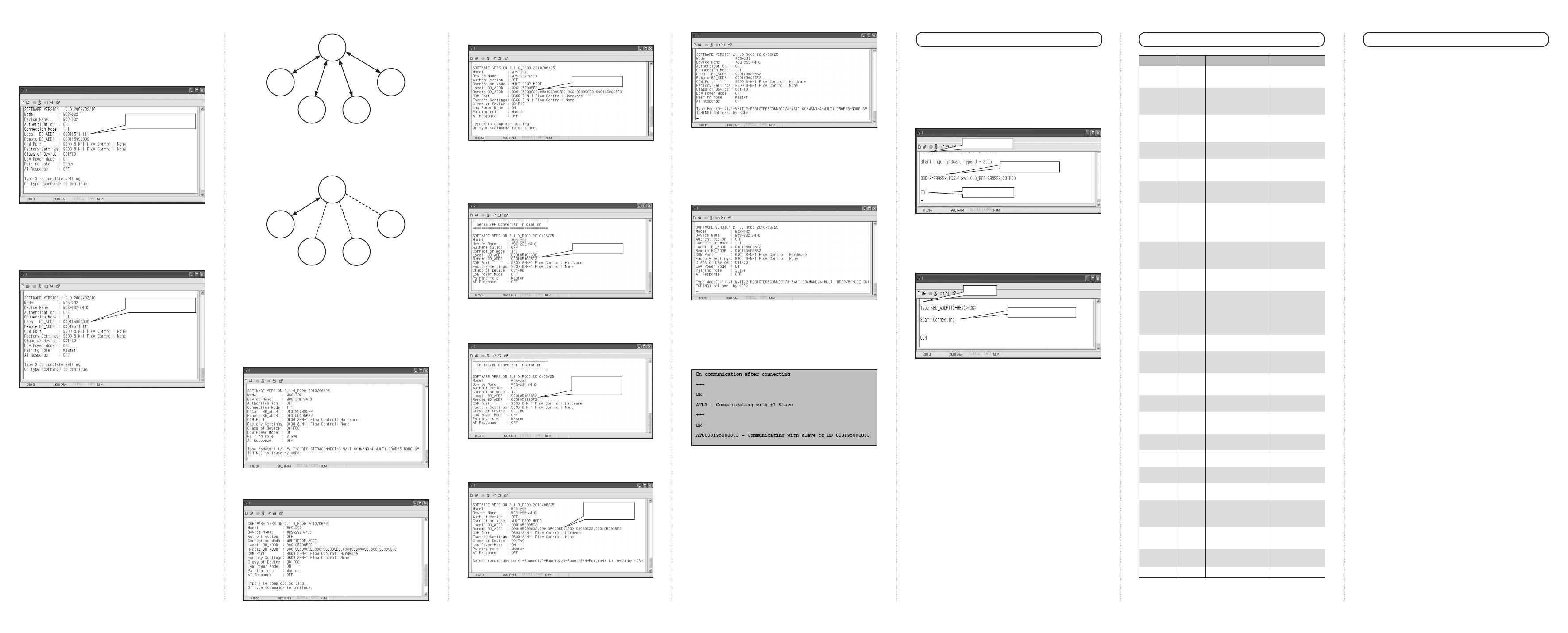
4) Multiple Connection mode (1:N) Communication
■
Overview
Although the WCS-232 is RS232, WCS-232 supports multiple
connections up to 4 slave units. There are two types of
multiple connection modes: Multi-Drop mode and Node-
Switching mode.
In Multi-Drop mode, the master can connect to maximum 4
slaves. At the same time, they transfer the data interactively
as below figure.
In Node-Switching mode, the master can connect to
maximum 4 slaves. But, only one connection with one slave is
active and the data is transferred as below figure.
■
Multi-Drop mode setting
You don’t have to use software program separately.
①
Set baud rate, data bits, parity and stop bit to 9600-8-
NONE-1 at Hyper Terminal.
②
Connect WCS-232 v4.0 used a master to your PC serial
port and put ‘Mode Switch’ to Setup Mode.
③
To use by Multiple Connection mode, change the 1:1 mode
with Multi-Drop mode.
(Type ‘M’ and type ‘4’ to select Multi-Drop mode.)
④
Save the setting using ‘X’ command and then put the ‘Mode
Switch’ to ‘Active”.
⑤
Record displayed Local BD_ADDR of the master.
⑥
Connect WCS-232 v4.0 used slaves to your PC serial port
and put ‘Mode Switch’ to Setup Mode.
⑦
Record displayed Local BD_ADDR of the slaves. (Note:
Maintain the status that master’s Hyper Terminal page
opened.)
⑧
Change the slaves’ Remote BD_ADDR with the master’s
Local BD_ADDR. (Set the master’s registered BD_ADDR
using ‘A’ command.)
⑨
Change the master’s Remote BD_ADDR with the slaves’
Local BD_ADDR. (Set the each slaves’ registered BD_
ADDR using ‘A’ command.)
⑩
Set the slaves’ mode not Multi-Drop mode but wait mode.
(Type ‘M’ and type ‘1’ to select wait mode)
■
Node-Switching mode setting
All processes are equal to Multi-Drop mode setting. But, the
difference is not ‘Multi-Drop mode’ but ‘Node-Switching mode’.
For example, in Multi-Drop mode, type ‘M’ and type ‘4’ to
select Multi-Drop mode. But, in Node-Switching mode, type
‘M’ and type ‘5’ to select Node Switching mode.
In Node-Switching mode, the master unit maintains multiple
connections with maximum 4 slave units but only one
connection with one slave unit is active and data is
transferred. Active slave is selected by AT commands. (Need
for software program)
■
Note
When large data exchange occurs in Multi-Drop mode without
flow-control enabled, the master unit may experience data loss. It
may also experience occasional disconnections and/or system
rebooting especially when bi-directional communication happens.
It is strongly recommended extensive performance test before
any real world field applications.
Node-switching mode provides nearly equivalent performance as
single connection mode. It is always recommended to use flow-
control for both of Multi-Drop mode and Node Switching Mode.
The Wait Mode that waits for a command by a user performs
search and connection of accessories. The correspondent
adapter shall be set up in Wait Mode.
■
Search
It searches Bluetooth devices connected and serviced in the
same coverage.
After execution of the command, the adapter address
searched is displayed
■
Connect
Connection to a specific device
After execution of the command, the ready of communication
is ended and the communication is enabled in Active Mode.
C-1. No Data Transmission
C-1-1. COM Port Settings
Check whether the Baud rate of WCS-232 v4.0 matches that
of its host equipment.
Check whether the host equipment has a Data bit setting of 8.
WCS-232 v4.0 supports only 8 Data bit settings. If your host
equipment uses 7 Data bit and even or odd parity, it may work
with a 8 Data bit and No parity setting. This is valid only when
both DCE devices are the WCS-232 v4.0. In this case, set
both WCS-232 v4.0] to 8 Data bit and No parity. If one of DCE
devices is another Bluetooth device such as Bluetooth USB
dongle,7 bit data configurations will not work.
Check whether the Parity and Stop bit of WCS-232 v4.0
match those of your host equipment. WCS-232 v4.0 supports
No parity, Even parity and Odd parity, 1 and 2 Stop bit
configurations.
Check whether the host equipment of WCS-232 v4.0 uses
Hardware Flow Control. WCS-232 v4.0 is initially set to Use of
Hardware Flow Control. If your host equipment does not use
Hardware Flow Control, please disable the Hardware flow
control option by referring to ‘5.Operating environment setting’.
WCS-232 v4.0 does not support RS-232 break signal.
C-1-2. Pin Assignment
WCS-232 v4.0 is a DCE device. If your host equipment is
DTE, plug WCS-232 v4.0 directly to the host equipment or use
straight RS-232 cable. If your host equipment is DCE, use will
need to use a cross over RS-232 cable (Null modem cable) or
a Male to Male DB9 Null Modem adapter.
C-2. Data Loss or Malfunctioning
C-2-1. Hardware Flow Control
When transmitting large amounts of data with No Hardware
Flow Control, WCS-232 v4.0 may clear the data buffer
unexpectedly. The possibility becomes greater as the RF
transmission environment becomes worse.
C-2-2. Response Message
AT response messages from the WCS-232 v4.0 may affect the
host system unexpectedly. Do not use WCS-232 v4.0 If your
applications cannot allow for this wireless time delay.
C-3. Transmission Delay
C-3-1. RF Processing Delay
It takes 30msec approximately for a WCS-232 v4.0 to
complete a data transmission to the other Bluetooth device.
This time delay cannot be reduced and may enlarge as the RF
transmission environment becomes worse. Do not use WCS-
232 v4.0 If your applications cannot allow for this time delay.
C-3-2. RF Transmission Environment
If there are many Bluetooth devices working in a small area
and/or the RF communication distance is too great and/or
there are some obstacles affecting RF performance, the WCS-
232 v4.0 repeats the transmission packet by packet due to
interferences and/or low RF performance. This may lead to
increased data transmission time delays.
Appendix–C : Trouble Shooting
Record BD_ADDR.
Enter BD_ADDR.
Appendix-A : Wait for user command mode
①
Input ‘T’
②
Input ”000195999999”
Input ‘I’ command
Device address found
Search completed
M
S1
S2
S3
S4
M
S1
S2
S3
S4
Record BD_ADDR
Record BD_ADDR
Enter the Master's
BD_ADDR
Enter the Slaves
BD_ADDR
Appendix-B : Command
Items
Commands
Descriptions
Remarks
※
User should change hyper terminal setting value as like Baud rate, Parity bit,
Stop bit to assigned factory default value in the Set-up mode, If user has
changed factory default’s setting value.
1. Connection
Setting
2. Baud Rate
Setting
3. PIN Number
Setting
4. Flow Control
Setting
5. Search Timeout
Setting
6. Maximum
Search Setting
7. Search
Execution
8. Search
Response
Setting
9. Power save
setting
10. Connection
Mode Setting
11. Name Setting
12. Parity Bit
Setting
13. Connection
Timeout Setting
14. Stop Bit Setting
15. Connection
Execution
16. Execution
Cancellation
17. Setting
Confirmation
18. CoD Setting
19. Setting Change
Save
20. Status Display
21. Help
22. AT Command
Response
23. Factory Reset
A(addr)
B(BR)
E(PIN
/ Enter)
F(FC)
G(TO)
H(NO)
I(TO,NO)
J(E/D)
K(E/D)
M(mode)
N(name)
P(PA)
Q(TO)
S(ST)
T(addr, [TO])
U
V
W(CoD)
X
Z
?([command])
L(E/D)
R
Setting for the address of device
to be connected
addr: 12 numbers in Hex
Setting for baud rate.
BR(Baudrate): 0 ~ 7
Setting for authentication /
ciphering.
PIN: 16 letters (max)
Enter: deactivated
Setting for flow control
FC: 0 ~ 1
Setting for search timeout
TO(timeout): 0 ~ 999
Setting for the maximum number
of devices to be searched
NO(Respondents): 0 ~ 999
Search for Bluetooth devices
connected
TO(timeout): 0 ~ 999
NO(correspondents): 0 ~ 999
Setting whether to respond to
search request
E: Enabled
D: Disenabled
Setting for power save mode
E: Enabled
D: Disenabled
Setting for connection mode
The default setting for WCS-232
v4.0 is connection mode 0, and
connection modes 1,2 are used
for the connection with other
Bluetooth devices.
Mode: 0 ~ 2
Setting for friendly name.
Name: 30 letters (max.)
Setting for parity bit.
PA: 0 ~ 2
Setting for timeout connection.
TO(timeout): 0 ~ 999
Setting for stop bit.
ST: 0 ~ 1
Connection to a specific device.
addr: 12 numbers in Hex
[TO](timeout): 0 ~ 999
Cancellation of device search
and connection command.
Displays current setting.
Setting for class of device.
CoD: 6 numbers in Hex
Applies edited settings.
Displays the status of WCS-232
v4.0.
Displays command list and help.
Setting whether to respond to AT
command
Setting for factory reset
0: 1200, 1: 2400
2: 4800, 3: 9600
4: 19200, 5: 38400
6: 57600, 7: 115200
After authentication and
ciphering, two adapters are
to be connected if their PIN
numbers are the same.
0: None
1: Hardware
Effective in connection
mode 2.
Default: 10 seconds
Effective in connection
mode 2.
Default: 10
Effective in connection
mode 2.
Search will be completed
when it reaches either
timeout or the maximum
number of correspondents.
Effective in connection
mode 1.
0: 1:1 connection
1: connection waiting
2: wait for user command
Along with the address, it is
available for ID.
0: None
1: Odd
2: Even
Effective in connection
mode 2
0: 1 Stop
1: 2 Stop
Effective in connection
mode 2
Effective in connection
mode 2
Software version
information included
Default: “001F00”
Critical factor for search
After command, WCS-232
v4.0 shall be rebooted.
S: Idle P: Pairing
C: Connecting
A: RF on
I: Inquiring
Commands shown are
depending on the Current
Mode.
AT command can be used
in mode 2