Solvline WCS-232 v5.0 User Manual
Page 2
User’s Manual
WCS-232 v5.0
User’s Manual
WCS-232 v5.0
User’s Manual
WCS-232 v5.0
User’s Manual
WCS-232 v5.0
9
7
10
8
11
12
13
14
7. Operation Environment Configuration
7.1 How to configure
Dedicated WCS-232 v5.0 configuration utility can
be used to modify communication speed, parity,
stop bit, device name, and operation mode.
■ Retrieve settings
① Connect WCS-232 to COM port and supply power to
the unit.
② Set switch in WCS-232 to Setup Mode.
③ Run WCS-232 v5.0 Setup Utility
④ From the utility, click Connection then COM Port at
the top of the menu to select the port to connect.
⑤ When successfully completed,
“Read from flash is
success
” message will appear.
■ Save settings
① Click Apply button to save the settings in the device
memory.
② After it is saved,
“Write to flash is success” message
will appear.
③ Click on the OK button to save the settings in the
device memory and close the windows.
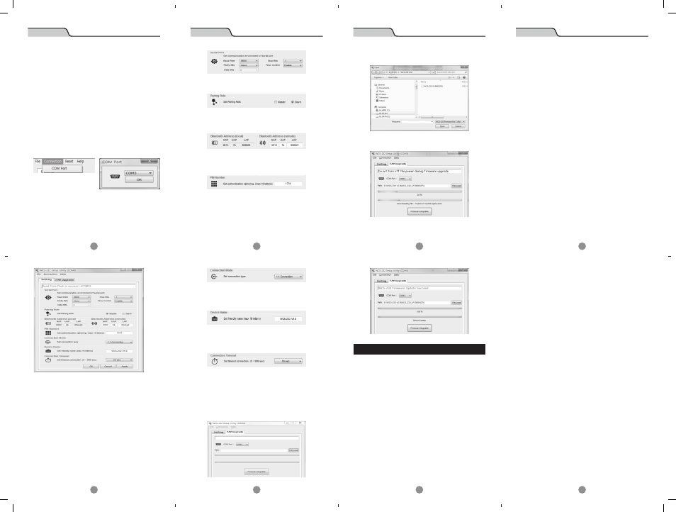
7.2 Operation Setting
■ Serial Port
Set serial communication configuration for SPP (Serial Port
Profile).
■ Pairing Role
Select Master/Slave mode
■ Bluetooth Address
Current Bluetooth address can be checked. The target
Bluetooth address can be checked and set.
■ Pin Number
When connecting to the Bluetooth device, this pin is required.
Up to ASCII 16 characters can be set for a pin number.
■ Connection Mode
WCS-232 v5.0 supports
“1:1 connection” and “connection
waiting
” modes.
In 1:1 connection mode, connection is established when
the address of the Bluetooth device is entered manually.
In connection waiting mode, When a target device is
not specified, it will look for new devices automatically.
■ Device Name
A device name can be given here with up to 16 ASCII
characters.
■ Connection Timeout
Set a given period of time until the Bluetooth device
searches and connects.
8. Firmware Upload
1. WCS-232 v5.0 unit and the DFU (Device Firmware
Upgrade) file is required to upload a firmware.
2. Select F/W upgrade tab.
3. When the
“File Load” button is clicked, following
dialog box will appear.
4. When you click on the
“Firmware Upgrade” button, it will
upload the firmware and show the progress from the bar.
5. After uploading the firmware is completed, the
following message will appear.
Appendix : Troubleshooting
1. Things to check when communication is not established.
1-1 COM port setting
• WCS-232 v5.0 supports 8 data bits only. When the
host supports 7 data bits and even or odd parity,
WCS-232 v5.0 can be set to 8 data bits, no parity
(factory default state). However, it cannot be applied
to a device such as 7 bit USB dongle.
• Check whether both WCS-232 devices are set to the
same parity and stop bit. WCS-232 supports v5.0 no,
even and odd parity and 1 or 2 stop bits.
• RTS (Request To Send) and CTS (Clear To Send) signal
from RS-232 standard are used for data transmit/
receiving (Hardware Flow Control or Hardware
Handshaking) control purpose.
• WCS-232 v5.0 does not support the break signal from
RS-232, thus it cannot be used for the device which
requires such feature.
1-2 Check the pin wiring
• Data transmit/receiving devices are separated to
DTE (Data Terminal Equipment) device and DCE
(Data Communication Equipment) device. Generally, a
terminal such as a PC is a DTE device and a data relay
system such as a modem is a DCE device. According
to RS-232 standard, when DTE device is required to
connect to a DCE device, two devices are connected
directly or by 1:1 cable.
In other words, signal lines such as TX and RX or
signal control line should not be crossed but connected
directly. However, when two same kind of devices,
such as DTE and DTE, or DCE and DCE devices needs
to be connected, cross cable (often called the null
modem cable) is used. This cable is used to connect
TX with RX signal lines and cross connect other
signal control lines.
WCS-232 v5.0 is a DCE device required to be connected
to a PC directly. Therefore, if it needs to be connected
to a DTE device, it can be connected to a DTE device
directly or use a 1:1 cable. However, if it needs to be
connected to a DCE device or a modem, a cross cable
is required to be used.
2. Data loss or dysfunction
2-1 Hardware control
• WCS-232 v5.0 sends a data received from the host to the
target Bluetooth device, but when the communication
environment is not good, resending packets will be
repeated resulting a delay in communication. When
a hardware flow control is not used, internal buffer
in WCS-232 v5.0 may receive more data than it can
handle, causing an overflow. Therefore when the
wireless environment is not good, it is recommended
to use the hardware flow control.
3. Delay in communication
3-1 Delay in converting to wireless signal
• When WCS-232 v5.0 converts a data from the
host to wireless signal, it takes about 30 msec.
This delay may be increased due to the wireless
connection environment. Additionally, when WCS-
232 v5.0 receives a data it converts to the wireless
signal immediately. Therefore, sequencing data can
be divided and transmitted. To prevent this, Inter-
Character Timeout feature is provided which is when
no data is received from the serial port, transmission
begins.
3-2 Wireless Environment
• The Bluetooth uses 79 channels to transmit a data
to avoid interferences. However, when there are
numbers of Bluetooth devices in a small area, trying
to send a large amount of data, data loss or error
may occur. WCS-232 v5.0 can use 1.2 AFH feature in
Bluetooth to avoid Wi-Fi interference, but depending
on the distance or the number of the devices, it may
have less effect in such environment.