SmarTek Systems SAS-1 Operating Modes and Architecture User Manual
Page 5
SmarTek Systems (www.smarteksys.com)
5
conductors and a continuous shield with a stranded shield conductor. For long runs, the long
home run cable used should be 22 gauge or larger.
The SAS-Cabinet Termination (SAS-CT) is a small circuit card (mounted inside the controller
cabinet or in a Type 170 card file) that provides the termination point for the home run cable
from the SAS-1. The home run cable is terminated with a high quality terminal block connector
that is plugged onto the SAS-CT. The SAS-CT provides electrical protocol conversion (RS-422
to RS-232) to facilitate connection to an RS-232 port of the cabinet controller or the RS-232 port
of the SAS-Relay Interface (SAS-RI). The SAS-CT provides a single stage of solid state surge
protection and additionally a stage of gas tube surge protection for all data and power lines.
The SAS-CT to Controller Serial Cable is used to connect the SAS-CT to the cabinet
controller via a modular (RJ-45) connector at the SAS-CT. The other end of the cable is a
modular (RJ-45), a DB-9, or a DB-25 connector depending on the controller or communication
device it is connected to.
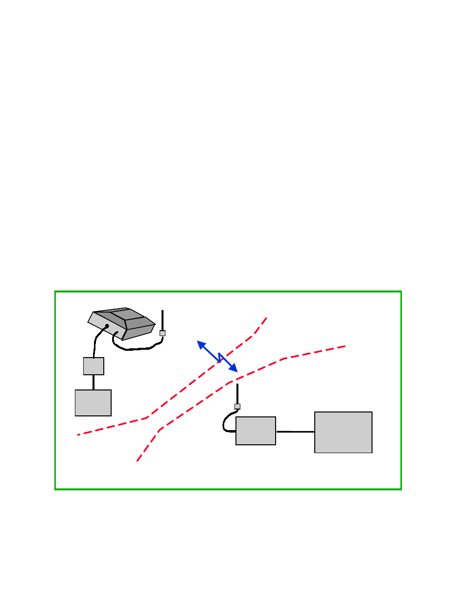
SAS-1 Wireless Link to Roadside Cabinet
A single SAS-1 unit or multiple SAS-1 units may be connected to a local controller/data
concentrator cabinet using wireless spread spectrum radio modems as shown in Figure 2. The
SAS-1 wireless option is implemented by putting the radio modem inside the SAS-1 cover or
using an external radio modem shared by multiple SAS-1 units. Hence, only power and antenna
cables are connected to the SAS-1 mounted on the roadside structure. To support the use of
Figure 2 SAS-1 Wireless Link to Roadside Cabinet
Multiple Wireless (2.4
GHz)
SAS-1s
SAS-JB
Base RF Modem
(2.4 GHz)
Cabinet Controller or
Controller Interface
- SAS Relay Interface
- SmarTek T-BOX
- Other Controller
Roadside Cabinet
Roadside Structure
RS-232
Solar/Battery
Cabinet