SmarTek Systems SAS-1 Intro and Background User Manual
Page 4
SmarTek Systems (www.smarteksys.com)
4
How “Acoustic Imaging” Is Accomplished
Vehicle generated acoustic signals (engine noise, fans, belts, tire noise, etc.) leave their source
(vehicle to be detected) and arrive at the SAS-1 (Figure 1) with an acoustic wave front which is
essentially flat. Each acoustic signal from each vehicle will arrive at the SAS-1 with a different
signal level and a different wave front angle (arrival angle).
The SAS-1 is comprised of an array of
rugged microphones, analog signal
conditioning, and sampling circuitry
for converting impinging acoustic
signal wave fronts to digital signals.
These digital signals are processed
using a programmable state of the art
Digital Signal Processor (DSP) with
associated memory and
communication circuitry. The
processing software implements
SmarTek Systems’ patented advanced
signal processing, spatial processing,
and vehicle detection algorithms. The
SAS-1 “listens to” and processes
every received acoustic signal
generated by passing vehicles or
stationary (idling) vehicles in real
time. The SAS-1 uses SmarTek
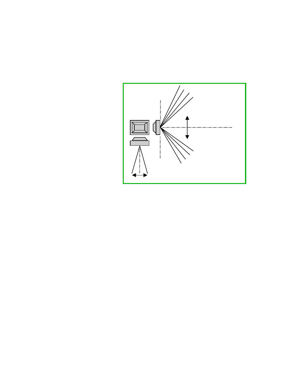
Systems’ advanced signal and spatial processing to create multiple acoustic signal arrival
direction channels (look directions) as shown in Figure 2. The SAS-1 implements 91 concurrent
listening channels (look directions) along it’s short dimension and a single listening channel
along it’s long dimension.
For multi-lane highway traffic monitoring, the SAS-1 is mounted roadside. It is oriented so
that the single listening channel is in the up/down road direction (SAS-1 mounting tube is
approximately parallel to the traffic flow) and the 91 listening channels (look directions) are in
the cross road direction as shown in Figures 1 and 3. In this configuration, the SAS-1 effectively
divides the highway (cross road) into 91 look directions from which vehicle sounds may
originate. The single up/down road look direction allows the SAS-1 to hear sound in a very
limited up/down road direction. It therefore, only hears vehicle sounds when the vehicle is
passing by the sensor station. As vehicle traffic moves or flows by the sensor station, the SAS-1
processing forms acoustic “images” or “blobs” of high signal intensity. This acoustic “image” is
presented as the Traffic Acoustic Image (TAI) display of the SAS Monitor and Setup software
(Figure 3). Each “blob” represents the acoustic “image” of a vehicle as it passes the SAS-1.
Up to five (5) SAS-1 detection zones are formed by selecting the position and number of
contiguous look directions which are combined for actual vehicle detection. This provides the
end user with unparalleled flexibility in choosing detection zone sizes and locations. For the
180
o
0 o
90
o
(Top View)
1 Look Direction ( 15 wide)
o
91 Look Directions
From 0 to 180
o
o
Figure 2 SAS-1 Look Directions