Central Hydraulics 66593 User Manual
Page 6
Page 6
SKU 66593
For technical questions, please call 1-800-444-3353.
one wheel and frame lifting points
when lifting the entire front or rear
end of the vehicle.)
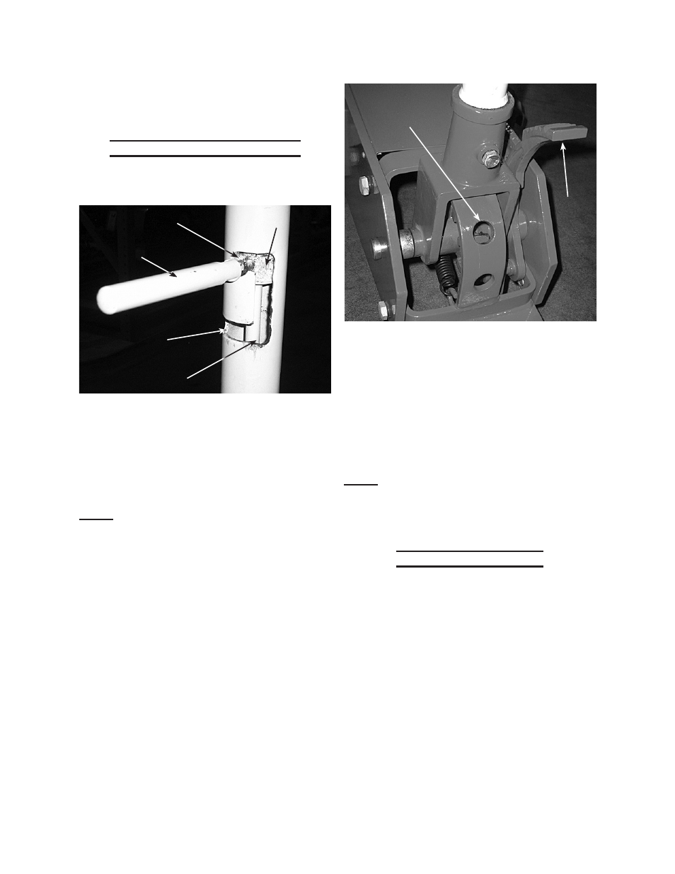
Handle Lever positioning:
Moving the Valve Release Lever (1.4)
1.
to the desired position. (See Fig. 2.)
Position D
Position C
Position A
Valve
Release
Lever
Position B
Fig 2
a.
position A: Shuts the Release Valve
allowing lifting of the Saddle (7.1)
by pumping the Handle (1.5) up and
down or pumping the Foot Pedal
(2.1).
Note: The Handle is not locked in this
position.
position B:
b.
The Deflector Rod (1.3)
is not engaged in the Base (2.6)
when at this position.
Fig 3
Positioning
Holes
Foot
Pedal
(2.1)
c.
position C: Allows the Deflector
Rod to drop into one of three holes
(See Fig. 3.) locking the Handle (1.5)
in one of three angles, vertical, hori-
zontal and 45°.
position d:
d.
Opens release valve to
lower the Saddle.
Note: With the release valve in its shut
position, the Foot Pedal (2.1) can be
pumped to raise the Saddle regard-
less of the Handle’s angle.
To raise the vehicle:
It is recommended to move the
1.
Valve Release Lever to Position B,
then move the Handle to the desired
angle.
The Valve Release Lever and De-
•
flector Rod will drop down into one
of three holes (at Position C) lock-
ing the Handle in either a vertical,
45° or horizontal angle.
Although the Foot Pedal (2.1) will
•
raise the Lift Arm (7.6), it is recom-
mended to lock the handle vertically
with the Valve Release Lever at Po-