Sigtronics SPE-2 User Manual
Page 2
CHASSIS INSTALLATION
Your TRANSCOM has been supplied with:
4 mounting grommets,
4 6/32” machine screws,
4 locking nuts
for mounting the intercom case.
1. Remove the 4 corner panel screws from the face panel.
2. Remove the intercom from the case.
3. After selecting a suitable mounting location in the aircraft, bore
four 1/4” holes in the case. (The TRANSCOM may be mounted
by securing to the case front or back sides, or bottom.)
4. Bore a 3/4” hole to provide a means of penetrating the case
with the 7 pin connector and cable. (If the front or rear case
surface is selected for the 3/4” hole, locate the hole toward the
case bottom to minimize interference between the cable and
intercom circuit board.)
5. Insert the 4 grommets into the 1/4” holes.
6. Drill aircraft with same hole pattern as in the intercom case, but
use a No. 27 drill. (Clearance drill for 6/32”)
7. Secure case to the aircraft with screw heads inside the intercom
case. (For circuit board clearance)
INSTALLATION INSTRUCTIONS: Please read the following instructions carefully so that you can derive maximum benefit from your SIGTRONICS TRANSCOM.
WIRING INSTRUCTIONS
Your TRANSCOM has been supplied with:
One 6 inch 7 conductor cable, terminated in a 7 pin connector, One
4 ft. 7 conductor mating cable, for wiring the unit to the aircraft.
The wires are color coded to conform with standard aircraft radio
color coding, where applicable.
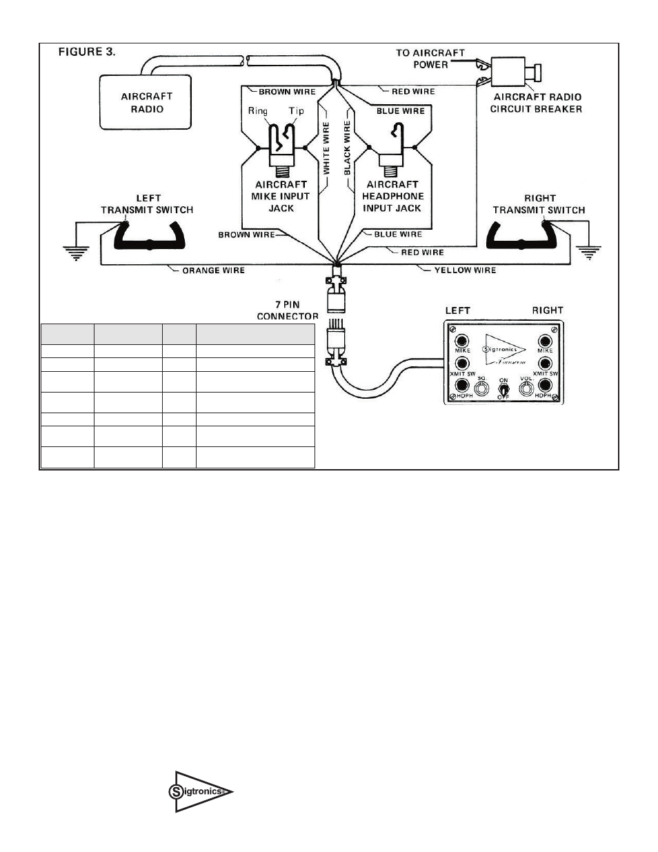
Figure 3 is a schematic illustration of the TRANSCOM wiring
connections to be made to the aircraft.
A Table is also presented in Fig. 3 which outlines the connector
pin numbers, along with the function, color and destination of
each wire in the cable. It is important to note that the orange and
yellow wires must be connected to the corresponding push-to-talk
switches as shown, because of the “opposite side disable” feature.
In addition, if the aircraft already has a push-to-talk switch hard
wired to the mike input jack, it must be disconnected from that
mike input jack and connected, as shown in Fig. 3 to the orange
wire. When wiring is completed, tape or otherwise insulate metal
parts on connector plug to prevent their contact with other aircraft
electrical equipment.
NOTE: Care should be taken to verify that the aircraft radio wiring
conforms to the standard color code.
A trimmer pot is provided inside the unit to adjust radio mike input
level. Appropriate adjustments can be made to compensate for
over or under modulation. Clockwise rotation increases mike output
level of intercom to radio.
NOTE:
1. If push-to-talk switch is connected to aircraft mike input jack, it must be
disconnected and connected to the orange wire as shown.
2. Orange wire must correspond to left mike input jack because of opposite
side cancel feature.
CONNECTOR
PIN NO.
FUNCTION
WIRE
COLOR
GOES TO
A.
Power
Red
Aircraft Radio Circuit Breaker
B.
Mike Output
Brown
Aircraft Mike Input Jack (Ring)
C.
Transmit Relay
control
White
Aircraft Mike Input Jack (Tip)
D.
Left Transmit
Switch Input
Orange
Left Transmit Switch
E.
Audio Input
Blue
Aircraft Headphone Jack
F.
Right Transmit
Switch Input
Yellow
Right Transmit Switch
H.
Ground
Black
Aircraft chassis or either Input Jack
Ground
Sigtronics Corporation
178 East Arrow Highway
San Dimas, CA 91773
Phone: (909) 305-9399
1-19-2007 perm2way.pdf