Eai-d4 / d6 ( dual radio ) wiring diagram, Figure 5 – Sigtronics EAI Installation Instructions User Manual
Page 7
Put on one of the headsets and position the boom mic close
to the mouth, as is the practice with hand-held microphones.
Voice clarity is best when the mic is about 1/4 inch away and
slightly off center from the lips. Turn the volume control on
the headset, all the way up (clockwise).
On the EAI unit, set both the intercom volume (VOL) control
and squelch (SQ) control to full clockwise position.
Now turn vehicle power on. Then turn the EAI power switch to
“ON”. Verify that you can now hear yourself in your headset.
Verify also that you can hear all the other headsets and that
they can hear you. If everything is OK, skip to the “PTT Test” on
page 8. Otherwise, if something is not working right, see the
following troubleshooting guide to find and fix the problem
before going on with the installation:
No Intercom In Any Of The Headsets:
1. Make sure the EAI power switch and VOLume and SQuelch
controls are set as above.
2. Make sure the vehicle power is on.
3. Check in-line fuse in EAI Radio 1/ Power Interface Cable.
4. Check power connection - red wire.
5. Check ground connection - green wire.
6. Check for short or open on headphone wire (Blue wire on
the Headset Jack and PTT Switch Cable). The problem could
be anywhere along the blue wire connection between the
headset jacks and the EAI unit.
Intercom In Some Headsets But Not In Others:
1. Make sure that EAI switch and controls are set as above.
2. Make sure that neither of the PTT buttons are pressed.
3. Make sure that neither of the PTT wires (white / red or
white / blue) are shorted to ground.
4. Check specific “bad” headset jack wiring for:
a) Microphone wire (jack ring terminal) open or shorted
to ground.
b) Headphone wire (jack tip wire) open or shorted to
ground.
c) Incorrect wiring - wires switched either at the jack or
at the point where the hookup wire connects to the
Headset Jack and PTT Switch Cable.
Loud Squeal In The Headsets All The Time:
1. First make sure all headset plugs are plugged in all the way
and that no part of any headset jack is physically touching
any metal.
2. Check headset jack wiring at all jacks. For example, incor-
rect wiring such as reversing the jack tip and ring wires will
cause a squeal.
7
Intercom
VOL
SQ
ON
RADIO 1
1234
RADIO 2
1234
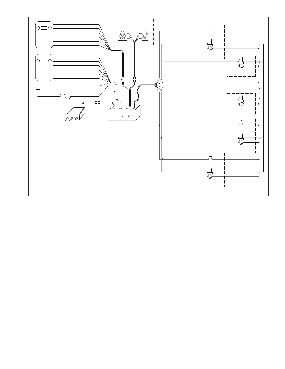
EAI-D4 / D6 ( DUAL RADIO ) WIRING DIAGRAM
NOTES:
1. CONNECT EITHER VIOLET WIRE TO THE RADIO SPEAKER HI OUTPUT. CONNECT THE
REMAINING VIOLET WIRE TO SPEAKER LO.
2. CONNECT EITHER WHITE WIRE TO THE RADIO PUSH-TO-TALK (PTT) KEY LINE INPUT.
CONNECT THE REMAINING WHITE WIRE TO THE PTT KEY LINE RETURN (PTT LO).
3. IF NEEDED, AN EXTENSION CABLE MAY BE FABRICATED AND INSERTED BETWEEN
P1 AND J1. PINS AND CONNECTORS HAVE BEEN SUPPLIED.
4. FOR EAI-D6 UNITS CONNECT PIN 13 (TAN) TO CREW #3 HEADSET JACK RING TERMINAL
AND PIN 14 (TAN) TO CREW #4 JACK RING TERMINAL. CONNECT BLUE AND BLACK
WIRES TO CREW #3 AND #4 AS ON OTHER JACKS.
5. MOUNT SWITCHES WITH BUSHING KEYSLOT DOWN.
FIGURE 5
CHASSIS GROUND
(8) GREEN
VOLTS DC
(7) RED
MIC LO
(4) BLACK
MIC HI
(1) BROWN
PTT LO
(6) WHITE NOTE 2
PTT HI
(5) WHITE NOTE 2
SPEAKER LO (3) VIOLET NOTE 1
SPEAKER HI (2) VIOLET NOTE 1
+12 / +24
FUSE
(1 AMP)
J3
P3
NOTE 4
NOTE 5
NOTE 3
P1 J1
J2
P2
(2) WHITE / RED
RADIO SELECT SWITCHES
TALK
RADIO 1
RADIO 2
LISTEN
AUTO
BOTH
(1) WHITE / BLACK
(8) TAN
(4) BLACK
(3) BLUE
(9) TAN
(10) WHITE / BLUE
(10) WHITE / BLUE
(11) WHITE / ORANGE
(11) WHITE / ORANGE
RADIO ADAPTER UNIT
INTERCOM UNIT
PTT SWITCH
HEADSET JACK
DRIVER
BARREL
TIP
RING
HEADSET JACK
CREW # 1
BARREL
TIP
RING
HEADSET JACK
CREW # 2
BARREL
TIP
RING
PTT SWITCH
HEADSET JACK
PUMP PANEL
BARREL
TIP
RING
PTT SWITCH
HEADSET JACK
CAPTAIN
BARREL
TIP
RING
Transmit
Radio 1
Mic Level
Radio 2
MIC LO
(4) BLACK
MIC HI
(1) BROWN
PTT LO
(6) WHITE NOTE 2
PTT HI
(5) WHITE NOTE 2
SPEAKER LO (3) VIOLET NOTE 1
SPEAKER HI (2) VIOLET NOTE 1
J4
P4
P5
J5