Sigtronics SDB-800 User Manual
Page 2
CHASSIS INSTALLATION
The Sigtronics’ Model SDB-800 consists of two complete units.
Figure 4 shows that each unit is completely independent from
the other except for power, ground, and the yellow wire. Each
half of the SDB-800 is designed to mount either horizontally
or vertically in your aircraft panel. All necessary mounting
hardware is supplied for 2-way through 8-way installation.
Hardware Supplied:
Eight Headphone Output Jacks - Accept standard .250” aircraft
headphone plug.
Eight Microphone Input Jacks - Accept standard .206” aircraft
microphone plugs (i.e. carbon, amplified dynamic or electret).
(U93 plug compatible jacks can be used in place of the jacks
provided).
Mike Jack Insulating Washers: 8 shoulder and 8 flat.
Two SDB-800 intercom panels lettered on both sides.
Control Knobs (4), Switch Nuts (2) 4-40 Screws (4)
Two drill templates: Hole size pattern for drilling aircraft
panel.
Two Aircraft / Intercom interface cables (4 feet long)
UNIT PLACEMENT
For ease of operation we recommend that you place the
pilot’s SDB unit on the pilot’s side of the aircraft panel and the
copilot’s unit should be placed on his side. This eliminates any
confusion about which half of the SDB-800 system each pilot
has to operate. Also, the location selected for each SDB unit
requires a minimum front panel area of 2-1/2” by 1- 1/16”. Depth
required behind panel is 4- 3/16” plus cable access.
CAUTION: Move aircraft flight controls through limits of travel
to make sure rear of intercoms and cables will not interfere with
aircraft control components.
PANEL PREPARATION:
1. Position adhesive template on aircraft panel in selected
areas.
2. Center punch each hole at cross lines. (The five holes are in
a straight line and are equally spaced 0.4” apart).
3. Drill 1/8” pilot hole all five places.
4. Enlarge holes to 1/4” and 3/8” per template.
5. Repeat above for the other SDB unit
MOUNTING CHASSIS: See Figure 2
1. Remove nut from SDB unit ON-OFF switch bushing.
2. Remove the 4-40 screws on either side of switch.
3. Remove Volume and Squelch control knobs. NOTE: DO
NOT REMOVE nuts from Volume and Squelch control
potentiometers.
4. Insert SDB unit from rear of aircraft panel with appropriate
arrow pointing upwards.
5. Install panel and lightly thread nut on to ON-OFF switch.
Nuts and washers on Volume and Squelch controls should
fit inside the 3/8” diameter holes.
6. Install two 4-40 screws through holes in intercom panel.
Tighten ON-OFF switch nut.
7. Install knobs on Volume (VOL) and Squelch (SQ) control
shafts using .050” Allen wrench.
8. Repeat for other SDB unit.
MOUNTING HEADPHONE AND MICROPHONE JACKS
1. Locate mounting areas. (One mike and one headphone
jack for each headset). Again, make sure the jacks will not
interfere with aircraft control components.
2. Drill 3/8” diameter holes for headphone jacks and install.
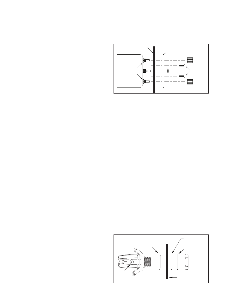
3. Drill 1/2” diameter holes for mike jacks and install with
insulating washers supplied. (See Figure 3).
NOTE: If the aircraft already has pilot headset jacks, they can be
used for the intercoms, but they must be rewired as follows:
Mike Jack:
1. Remove any existing wires from the tip, ring, and barrel
connections.
2. Connect the intercom white / black wire to the ring
terminal.
3. Connect one end of a ground wire to the barrel terminal of
the mike jack and connect the other end to Point A.
4. Install insulating washers as necessary if the barrel of the
mike jack is mounted in metal. These are not necessary for
function, however they reduce the possibilities of ground
loop induced noise.
For the headphone jack: add the appropriate blue wire to
the tip terminal. No need to remove existing wires on the
headphone jack.
��������
�����
���� ���� ��
������
���
��������
�� ��� ������
����� ����
����
����
AIRCRAFT
PANEL
FIGURE 2
��������
������
����
���������
������
����
�����
������
���
��������
�����
����
������
���
FIGURE 3