Res-2 installation drawing figure 1, Sigtronics corporation – Sigtronics RES-2 User Manual
Page 2
CHASSIS INSTALLATION
Select a mounting location which will not cause interference with
flight controls. Four 6/32” screws with self locking nuts have been pro-
vided for mounting the chassis to the aircraft.
1. Remove the unit from the case.
2. After selecting a suitable mounting location in the aircraft, drill air-
craft and switcher case with the same hole pattern. Use a No. 27 drill
(Clearance drill for 6/32”).
3. Secure case to the aircraft with the screw heads inside switcher case
for circuit board clearance.
4. Replace the unit in the case and secure.
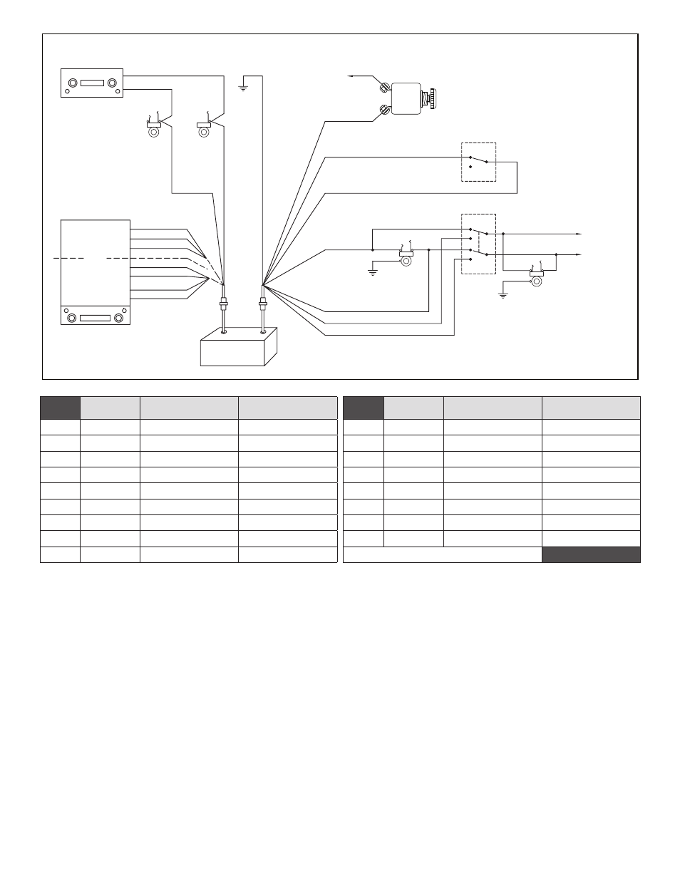
WIRING INSTRUCTIONS
Four feet of cable has been provided to connect the unit to the aircraft
and entertainment system.
Figure 1 illustrates the connections to be made.
Table 2 lists the connector plugs and pin numbers, the color, function
and destination of each wire connected to those pins. Connections
should be made as shown in Figure 1 and as indicated in Table 2.
Sigtronics should be contacted if other means of connecting the unit
are contemplated.
OPERATING INSTRUCTIONS
Step 1. Turn aircraft radio “ON” and adjust both squelch (if manual)
and volume to suitable listening level.
Step 2. Turn Audio Switcher and entertainment system “ON” and
adjust entertainment to suitable listening level.
Step 3. Select Pilot or All position to suit switching mode desired.
Note: The Switcher controls can be changed from one mode to
another at any time. (See Mode Selection Table 1)
TRANSMIT: Transmitting is accomplished in the conventional manner,
by using your headset or hand-held microphone. Messages are received
via the headphones being worn. If the pilot has a headset with a boom
microphone and uses a push-to-talk switch, then the headset micro-
phone plug should be connected to the aircraft microphone jack and
the headphone should be connected to the switcher headphone jack.
Sigtronics Corporation
178 East Arrow Highway
San Dimas, CA 91773
10-27-2014 res2inst.pdf
Phone: (909) 305-9399
E-mail: [email protected]
Web Site: www.sigtronics.com
page
2
INTERCOM
CIRCUIT
BREAKER
(1 AMP)
RES-2 Installation Drawing
Figure 1
Notes:
1. Pilot / All switch and Passenger jacks not
used in single headset installations.
2. For mono headsets, remove wire from
headphone ring terminal and connect to
headphone tip terminal.
To other
Passenger
headphone
jacks
Aircraft Interface Area
Headphone Audio
A / C Ground
Radio Mic Key
( J1-5 ) White
( P2-2 ) White / Red
( P2-1 ) White / Red
( P2-4 ) White / Green
( P2-6 ) White / Black
( P2-3 ) Green
( P2-5 ) Gray
Yellow ( J1-2 )
W / Yellow ( J1-3 )
W / Brown ( J1-9 )
W / Violet ( J1-8 )
Orange ( J1-1 )
Black ( J1-4 )
Violet ( J1-7 )
Stereo
Or
Headphone
or
Line Level
Output
Speaker
Output
RES-2
Music Switcher
J1
P1
P2
J2
Right
Common
Left
Right +
Right –
Left +
Left –
( J1-6 ) B
lue
( P2-8 ) B
lack
Tip
Tip
Tip
Ring
Ring
Barrel
Tip
Ring
All
Barrel
Aircraft
Hand Mic
Jack
Aircraft
Headphone
Jack
To Aircraft
Power Buss
12 / 28 VDC
Pilot
Headphone
Jack
Pilot
On
Off
Passenger
Headphone
Jack
Aircraft Radio
12345
( P2-7 ) Red
J1
Pin #
Wire
Color
Function
Connect To:
P2
Pin #
Wire
Color
Function
Connect To:
J1-1
Orange
HDPH / Line output
Left Channel
P2-1
White / Red
Music ON / OFF
Music Switch ON
J1-2
Yellow
Speaker Output
Left Channel Positive
P2-2
White / Red
Music ON / OFF
Music Switch Common
J1-3
White / Yellow
Speaker Output
Left Channel Negative
P2-3
Green
Pilot Right Channel
Pilot Jack Tip
J1-4
Black
HDPH / Line Common
HDPH / Line Common
P2-4
White / Green
Passenger Right Channel
Pilot / All Mode Selector SW
J1-5
White
XMIT Music Disable
Tip of Aircraft Mic Jack
P2-5
Gray
† Pilot Left Channel
Pilot Jack Ring
J1-6
Blue
Headphone Audio input
output Jack Tip
Aircraft Radio Headphone
P2-6
White / Black
Channel
† Passenger Left
Selector SW
Pilot / All Mode
J1-7
Violet
HDPH / Line output
Right Channel
P2-7
Red
Power Input
Aircraft Circuit Breaker 1 Amp
J1-8
White / Violet
Speaker Output
Right Channel Positive
P2-8
Black
Ground
Aircraft Ground
J1-9
White / Brown
Speaker Output
Right Channel Negative
Note: † Relevant to Stereo Installation
Table 2