Igtronics – Sigtronics SPA-4SN Installation Instructions User Manual
Page 4
igtronics
®
S
(12) VIOLET
TO
TO
To SPA-4SN
J1 Pin 12
Push-To-Intercom Switches
( 1 Per Headset )
A
A
Figure 8
Figure 7
page 4
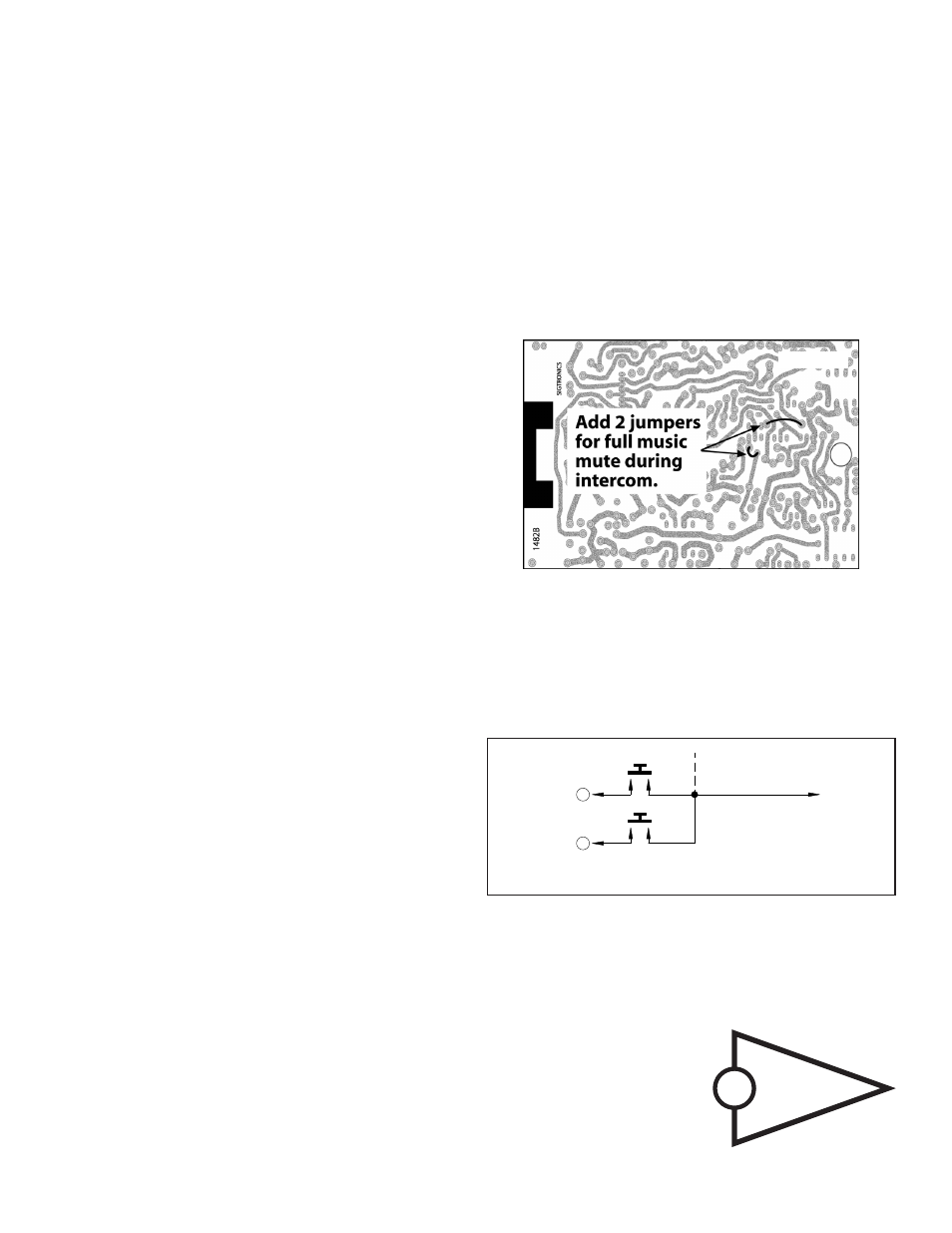
HOW TO SELECT MUSIC OPTION
T
o select full music mute during intercom, the unit must be removed from
the aircraft. This is done by first removing the volume and squelch control
knobs with a 0.05 inch Allen wrench. Then remove the two mounting screws
and switch nut that holds the unit in the panel. The unit is now free for
removal from the aircraft after disconnecting the cables at the plugs.
To enable this option, modification to the bottom of the units’ circuit board is
required. CAUTION – a qualified technician should perform this modification.
First remove the three screws securing the bottom cover to the case and
carefully lift and remove the cover. Note that the circuit board does not have
to be removed from its case to complete the modifications.
To select full mute during intercom solder the two small-insulated jumper
wires at the locations specified in Figure 7.
Replace the cover and secure it with the three screws as before. Install the
unit back into the panel and plug in the two cables.
SPA-4SN PUSH-TO-INTERCOM INSTRUCTIONS
Install a separate momentary switch at each headset position. Connect
per Figure 8. To use the push-to-intercom feature, turn the squelch control
on the intercom fully counter-clockwise. Then to activate, press the push-
to-intercom switch(s). Alternately, to use the intercom in voice activated
(VOX) mode set the intercom squelch as normal. See the separate SPA-4S
OPERATING INSTRUCTIONS sheet.
INSTALLATION CHECK-OUT AND ADJUSTMENTS
After the unit is installed, again check that the SPA-4S unit chassis, jacks,
and wiring harness are clear of all aircraft operating controls and cause no
interference with them. Next, to check out the SPA-4S unit installation, plug
in all the headset mic and phone plugs into the respective intercom jacks.
Put on the pilot’s headset and position the boom mic close to the mouth.
Voice clarity is best when the mic is at one side of the mouth and 1/4” from
the lips.
To assure that the aircraft radios, pilot’s headset, and PTT switch are
connected and functioning properly, switch the SPA-4S ON/OFF switch to
the “off” position. If applicable, set the aircraft audio panel to “Headphone”
position. Then turn on the aircraft radio(s) as usual, and verify that the pilot
can hear the radios and can transmit using his push-to-transmit switch and
headset. Aircraft radio(s) and audio panel should operate exactly as they
did before the SPA-4S system was installed. Aircraft radio reception should
also be heard in the co-pilot and passenger headsets. There should be no
intercom between headsets with the SPA-4S unit “off”. Next turn the SPA-4S
unit “on”. Set the SPA-4S volume control to mid-position. Set SPA-4S squelch
control fully clockwise. Verify that the Pilot and co-pilot can operate the
aircraft radio(s). As before, all headsets on the intercom will hear the aircraft
radio(s). Check that all headset positions can intercom.
Mic Output Adjust
It may be necessary at this time to adjust the SPA-4S unit mic output to
the aircraft radios. A small adjustable potentiometer is provided inside the
unit for this purpose. It is accessible through a hole in the side of the SPA-
4S chassis. It is marked “Mod. Adj.”, and can be adjusted with a small blade
screwdriver. In the event of over-modulation (garbled) or reports of weak
transmissions over the aircraft radio, an appropriate adjustment can be made.
Clockwise rotation increases the output level to the aircraft radio mic input.
Counter-clockwise rotation decreases modulation level. This adjustment
sometimes needs to be made after the initial installation of the intercom or
if a new radio is installed. (The output is set for unity gain at Sigtronics).
Radio Receive Adjust
It may also be necessary to adjust the unit radio receive input from the aircraft
radio. A small adjustable potentiometer is provided inside the unit for this
purpose. It is accessible under a sticker on top of the chassis box (see Figure
4), and can be adjusted with a small blade screwdriver. In the event of low
aircraft radio volume in the “ON” mode relative to “OFF” mode, an appropriate
adjustment can be made. Clockwise rotation increases the input level to the
SPA radio receive input. Counter-clockwise rotation decreases input level.
This adjustment sometimes needs to be made after the initial installation of
the intercom or if a new radio is installed that has a low output impedance or
low output power. The adjustment is best made with all headsets plugged in.
(The input is set full CCW which is unity gain for 500
Ω radios). Note: Be sure
to replace the sticker when you have completed the adjustment.
You are now ready to check for proper wiring of the music source. First, make
sure squelch is off (full counter clockwise) and intercom is ON. Turn on the
music source and listen for music through pilot and co-pilot headsets, and
passenger headsets. There should be music.
If everything checks out, refer to the SPA-4S OPERATING INSTRUCTIONS
sheet for proper use and other operating modes of the Sigtronics SPA-4S
intercom system. If something does not work as described, carefully go over
the intercom wiring again. If something is still not right or you have any
questions regarding the installation and operation of the Sigtronics SPA-4S
intercom or any other Sigtronics product feel free to contact us directly or
E-mail us at [email protected]. Technicians are available Monday though
Friday 8 am to 4:30 PM Pacific time.
See the separate SPA-4S OPERATING INSTRUCTIONS sheet for complete
operation information.
Sigtronics Corporation
178 East Arrow Highway
San Dimas, CA 91773
(909) 305-9399
www.sigtronics.com
spa4sins_h.pdf SPA4SINST REV H 3-27-2009
FAA TSO: C50b ENV. CAT (DO-160) CFBBBX