Page 3, J2 pin wire color function connect to – Sigtronics RES-601 Installation Instructions User Manual
Page 3
���������
��
���� �����
������
�������
������
����� �
���� �
����� �
���� �
�����
������
����
�������� ������
������� ������
������ ������
������ ������
������ ������
����� ������
�������� ������
������
��
������� � �������
��������
���
��
��
�������� �������
��
��
�� ��
��
��
���� �
������� � �������
����� ��������
��
��
��
���
���
�����
����� ��������
���� �
�������� ������� ������
� �������� �� ������� ��� ������ ����� �����
�� �� ��� ��� ��� ������� �� ������ ���� ���
�� ����� �������� ���� ������� �������� �����
������
�� �� ������������ ������ �� ��������� �� ��������
��������� �� ��� ��������� ���� �� ������
���� ��� ����� �� ���� �� ������������ ���
������ ������ ������
�� ����� �� � ��
��������� ������
������ �
��������
�������
�������
�� ����
�� ��������
����� ����
����� ���
����������������� ��������� ����
���
����
����� �
���������
�������
������
������
��
��
��
�
��
�
�
������ ���������
������ �����������
������� ������������
������ ���
������ ����
������ �����
��
��
��
��
�
������� ����������
������ �����
��������
���� ���
����
��������
���������
����
��� �����
��������� �����
����� ��� ���
�������� �����
�����
���
�
��
�
��
���� �
�����
��� ������
��������
��� ������
�
��
����
������
���
��������
��� ����
������
���
����
��������
��������� ����
�
��
������
���
����
�����
��� ����
��
��
��
��
�
������
���
����
������ ����
�����
��������� ����
����
�����
������������� ������������ �������
������ �����
������� ����
������� ����
�� ����� �� ��� �����
�� ����� �� ��� �����
������
���
������
���
����
�
��
����
��������� ����
��� ����
��������� �
��������� ����
������
���
������
���
����
��� ����
�
��
��������� �
����
page 3
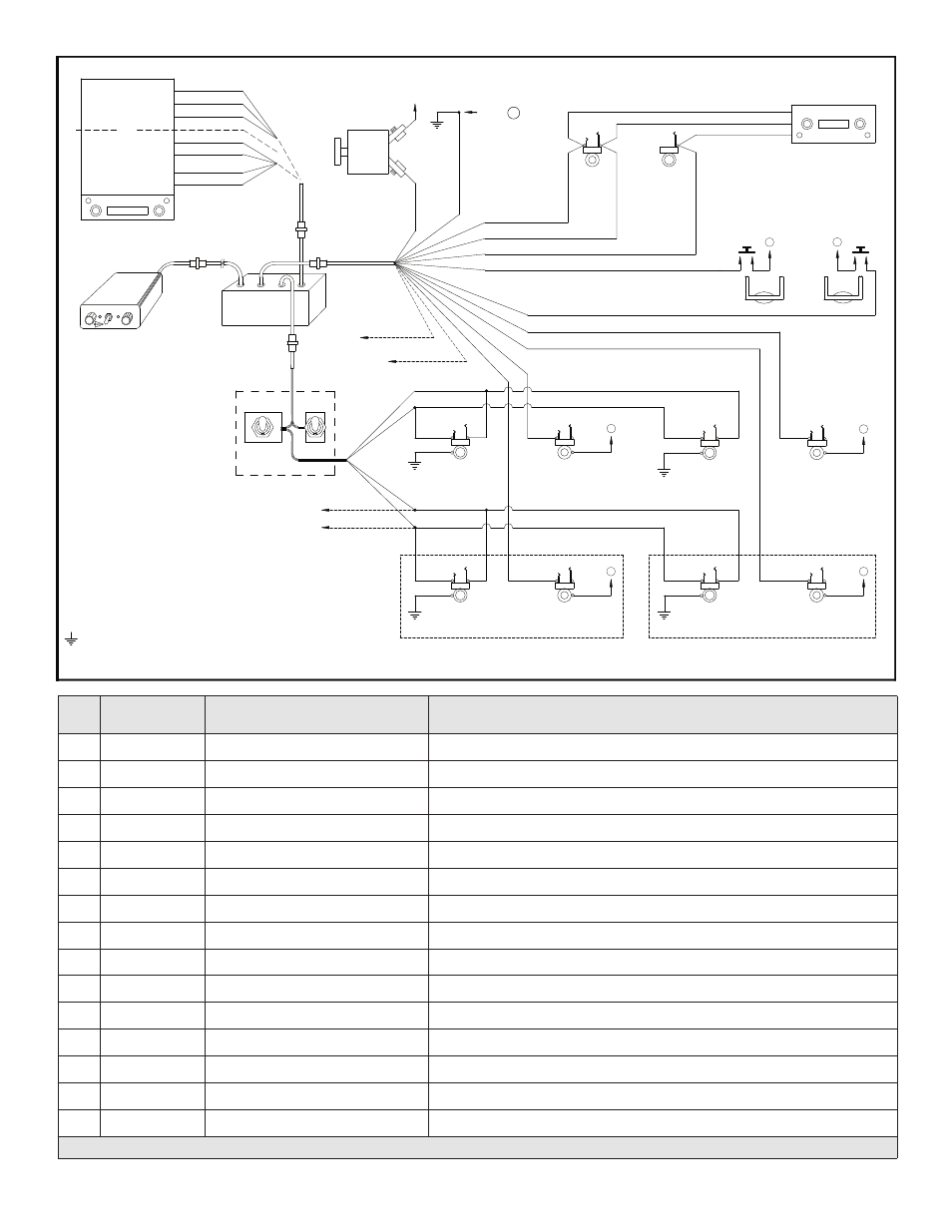
J2
PIN WIRE COLOR
FUNCTION
CONNECT TO:
1
White / Black
Pilot Mic Input
Ring Terminal of Pilot Mic Jack
2
White / Red * 8 Pilot Transmit Switch Input
Pilot Transmit Switch (PTT). Switch to Ground to Transmit.
3
Blue
* 3 Radio Headphone Input
Radio Headphone Output
4
Black
* 4 Intercom Ground
Aircraft Chassis Ground – Central Grounding Point “A”
5
White
* 8 Radio Transmit Key Output
Radio or Audio Panel Transmit Key Input
6
Brown
Transmit Mic Audio Output
Ring Terminal of Hand Mic Jack or Mic Input of Radio or Audio Panel
7
Red
* 5 Power Input (12 through 28 VDC)
Intercom Circuit Breaker
8
Tan
* 6 Passenger #1 Mic Input
Ring Terminal of Passenger #1 Mic Jack
9
Tan
* 6 Passenger #2 Mic Input
Ring Terminal of Passenger #2 Mic Jack
10
White / Blue * 8 Co-Pilot Transmit Switch Input
Co-Pilot Transmit Switch (PTT)
11
White / Orange
Co-Pilot Mic Input
Ring Terminal of Co-Pilot Mic Jack
12
—
—
—
13
Tan
* 6 Passenger #3 Mic Input
Ring Terminal of Passenger #3 Mic Jack
14
Tan
* 6 Passenger #4 Mic Input
Ring Terminal of Passenger #4 Mic Jack
15
—
—
—
TABLE 1 * See corresponding number paragraphs under the “WIRING INSTRUCTIONS” section starting on page 4.