Sandia Aerospace SAFE 128 User Manual
Page 2
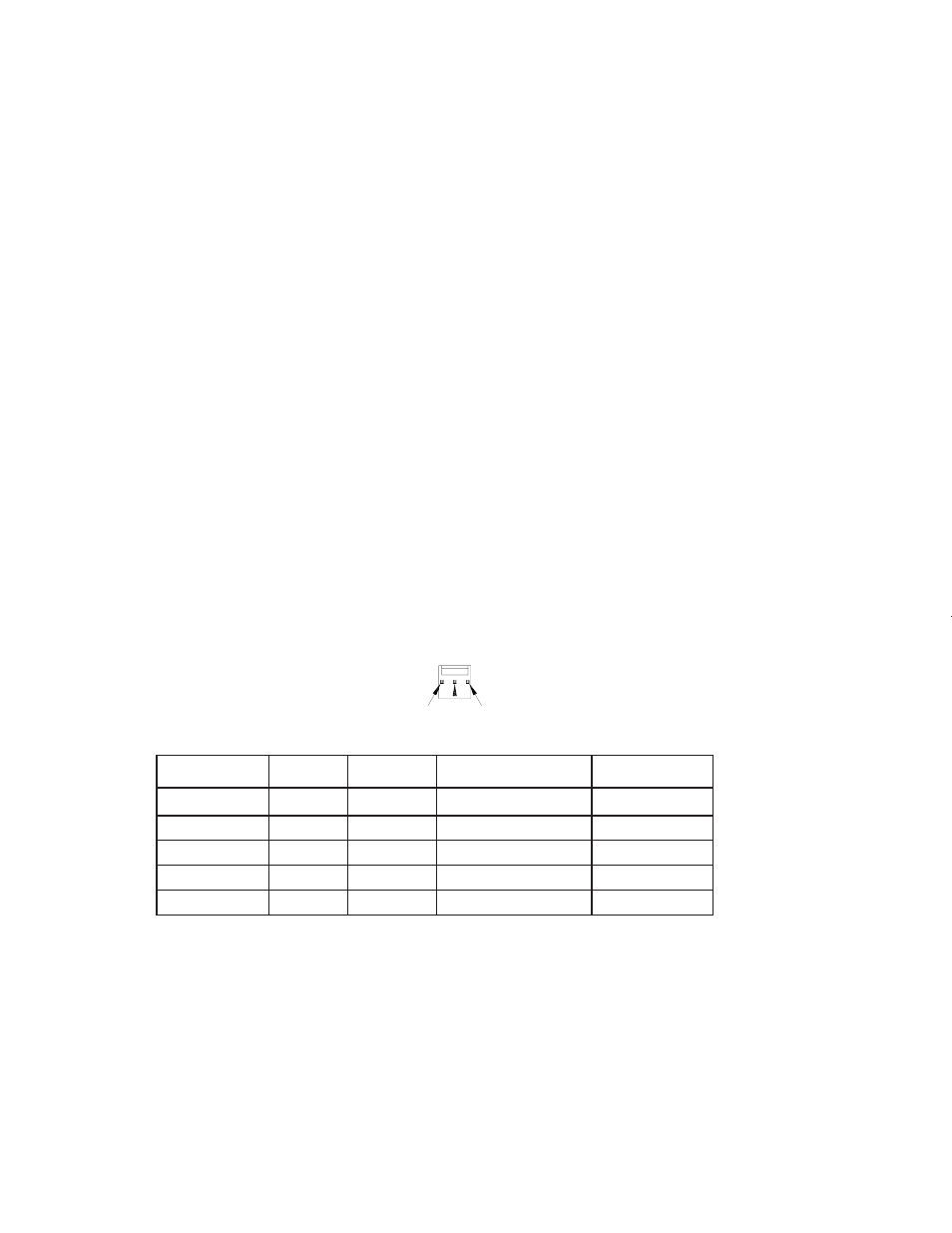
The SAFE 128 operates on 28Vdc. It will provide a low on Fan Fail (center pin) of the connector when
operating normally. When airflow drops to 60% of nominal, as determined by fan RPM, Fan Fail will output a
high. An external pull-up is required. Power to the SAFE 128 can be supplied from the aircraft buss or from
the unit to be cooled if an ouput is available. If connected to the aircraft buss, the SAFE 128 should be pro-
tected by a .5 amp fuse or breaker.
2.5
C
ALIBRATION
No calibration of the SAFE 128 is required. The unit can be tested by slowing the fan manually and observing
a high present on the Fan Fail pin. Allow the fan to return to normal speed and observe a low on the Fan Fail
pin.
2.6
C
ONTINUED
A
IRWORTHINESS
Maintenence of the SAFE 128 is on condition only. No scheduled maintenance is required.
2.0
INSTALLATION PROCEDURES
2.1
G
ENERAL
The SAFE 128 is supplied with a mounting connector and four contacts. Only three contacts are required and
the spare one is provided in case one is destroyed during installation. The SAFE 128 is also shipped with a
mating connector attached to the unit itself. This is to protect the pins during transit. This connector can be
discarded once the unit is received or may be retained to cover the pin in case return shipment to the factory is
necessary. The SAFE 128 is mounted with four (4) number 6 or 8 screws.
2.2
E
QUIPMENT
R
EQUIRED
2.2.1
Supplied
SAFE 128 System
Includes:
SAFE 128 Fan
305468-00
Installation Kit
305477-00
Mating Connector
305479-03
Mating Pins
305478
2.2.1
R
EQUIRED
BUT
NOT
SUPPLIED
Four (4) Number 6-32, 8-32 or equivalent mounting screws
2.3
M
OUNTING
The SAFE 128 mounts with four number (4) 6-32 or 8-32 or equivalent machine screws. Be sure to observe
the direction of airflow.
2.4
E
LECTRICAL
n
o
i
t
p
i
r
c
s
e
D
r
e
r
u
t
c
a
f
u
n
a
M
r
e
b
m
u
N
s
e
i
r
e
S
r
e
b
m
u
N
t
r
a
P
.
f
n
a
M
r
e
b
m
u
N
t
r
a
P
a
i
d
n
a
S
g
n
i
s
u
o
H
r
o
t
c
e
n
n
o
C
x
e
l
o
M
5
9
6
2
7
3
0
3
-
1
-
2
2
3
0
-
9
7
4
5
0
3
t
c
a
t
n
o
C
p
m
i
r
C
x
e
l
o
M
9
5
7
2
4
1
1
0
-
0
5
-
8
0
8
7
4
5
0
3
l
o
o
T
r
e
p
m
i
r
C
d
n
a
H
x
e
l
o
M
A
N
C
2
6
2
2
R
C
r
o
5
8
1
0
-
1
0
-
1
1
*
A
N
l
o
o
T
n
o
i
t
c
a
r
t
x
E
x
e
l
o
M
A
N
2
2
0
0
-
3
0
-
1
1
*
A
N
l
o
o
T
n
o
i
i
t
r
e
s
n
I
x
e
l
o
M
A
N
0
0
0
0
-
2
1
8
3
6
*
A
N
*or equivalent
Mating Connector and Contact Information
Gnd Fan
Fail
Pwr
305468-00-IS
Rev B 09/26/06
DRN 287