Ad12-16(pci)e, Ver.3.10, 4connector pin assignment – Contec PC-I Bus Analog Input Multi Function Board AD12-16PCIE User Manual
Page 4
Ver.3.10
AD12-16(PCI)E
4
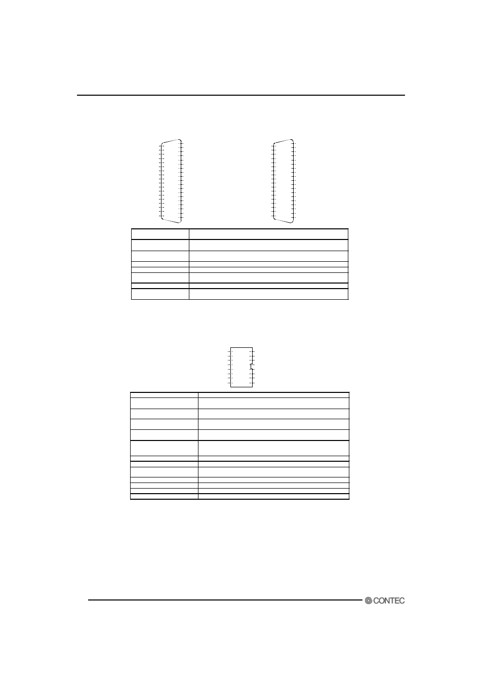
Connector Pin Assignment
CN 1
19
18
17
16
15
14
13
12
11
10
9
8
7
6
5
4
3
2
1
Di git al Ground
Analog Gr ound
Analog Gr ound
Analog Gr ound
Analog Gr ound
Analog Gr ound
Analog Gr ound
Analog Gr ound
Analog Gr ound
Analog Gr ound
Analog Gr ound
Analog Gr ound
Analog Gr ound
Analog Gr ound
Analog Gr ound
Analog Gr ound
Analog Gr ound
Analog Gr ound
37
36
35
34
33
32
31
30
29
28
27
26
25
24
23
22
21
20
+5V DC f rom PC
Simul t aneous Hol d Out put
Analog Out put
Analog I nput
7 [-]
Analog I nput 7 [+]
Analog I nput
6 [-]
Analog I nput
6 [+]
Analog I nput 5 [-]
Analog I nput
5 [+]
Analog I nput
4 [-]
Analog I nput
4 [+]
Analog I nput
3 [-]
Analog I nput
3 [+]
Analog I nput 2 [-]
Analog I nput
2 [+]
Analog I nput 1 [-]
Analog I nput
1 [+]
Analog I nput 0 [-]
Analog I nput
0 [+]
CN1
19
18
17
16
15
14
13
12
11
10
9
8
7
6
5
4
3
2
1
D igi t al Gr ound
Analog G round
Analog G round
Analog G round
Analog G round
Analog G round
Analog G round
Analog G round
Analog G round
Analog G round
Analog G round
Analog G round
Analog G round
Analog G round
Analog G round
Analog G round
Analog G round
Analog G round
37
36
35
34
33
32
31
30
29
28
27
26
25
24
23
22
21
20
+5V DC f r om PC
Simultaneous Hold Output
Anal og Out put
Anal og I nput 15
Anal og I nput
7
Anal og I nput 14
Anal og I nput
6
Anal og I nput 13
Anal og I nput
5
Anal og I nput 12
Anal og I nput
4
Anal og I nput 11
Anal og I nput
3
Anal og I nput 10
Anal og I nput
2
Anal og I nput
9
Anal og I nput
1
Anal og I nput
8
Anal og I nput
0
<
Single-Ended Input
>
<
Differential Input
>
Analog Input 0
to Analog Input 15
Analog input signals in single-ended input mode.
The numbers correspond to channel numbers.
Analog Input 0[+]
to Analog Input 15[+]
Analog input signals in differential input mode.
The numbers correspond to channel nu mbers.
Analog Input 0[-]
to Analog Input 15[-]
Analog input signals in differential input mode.
The numbers correspond to channel numbers.
Analog Output
Analog output signal
Analog Ground
Analog ground common to analog I/O signals.
Simultaneous Hold
O u t p u t
Control signal for simultaneous sampling unit ATSS -16 available as an
option.
+5V DC from PC
Supplies 3 amperes of current at +5 volts.
Digital Ground
Digital ground common to "Simultaneous Hold Output" and "+5V DC from
PC".
Notes!
- Please connect each output and power s upply output neither with analog ground nor digital gr ound too hastily.
- Moreov er, please do not connect output and output. It becomes the cause of failure.
CN2
A8
A7
A6
A5
A4
A3
A2
A1
B8
B7
B6
B5
B4
B3
B2
B1
+5V D C fr om PC
Sampl ing Clock Out put
Ext er nal St op Tri gger I nput
Di gi t al I nput 3 / I N T Tr igger
Di gi t al I nput 1 / CNT Gat e
Di gi t al Gr ound
Di gi t al Out put 2
Di gi t al Out put 0
N . C.
Di gi t al Gr ound
Ext er nal Sampli ng Cl ock I nput
Ex t ernal St ar t Tri gger I nput
Digit al I nput 2 / CN T Cl ock
Digit al I nput 0
D igi t al Out put 3 / CN T Out put
Digit al O ut put 1
Digital Input 0 Digital input signal.
Digital Input 1
/CNT Gate
Digital input signal.
Also serving as the counter gate control input signal.
Digital Input 2
/CNT Clock
Digital input signal.
Also serving as the clock input signal
Digital Input 3
/INT Trigger
Digital input signal.
Also serving as the interrupt input signal.
Digital Out 0
to Digital Out 2
Digital output signal.
Digital Out 3
to C N T O u t p u t
Digital output signal.
Capable of being jumper-switched to serve as the counter output
signal.
External Start Trigger Input
External trigger input signal for sampling start conditions
External Stop Trigger Input
External trigger input signal for sampling stop conditions
External Sampling Clock
Input
External sampling clock input signal
Sampling Clock Output
Sampling clock output signal
+5V DC from PC
Supplies 1 ampere of current at +5 volts.
Digital Ground
Digital ground common to the signals and “+5V DC from PC”.
N.C.
No connection to this pin.
Notes!
- Please connect each output and power s upply output neither with analog ground nor digital gr ound too hastily.
- Moreov er, please do not connect output and output. It becomes the cause of failure.