Dvbr series direct vent gas fireplace, Hearth, Framing and finishing – Vermont Casting DVBR42 User Manual
Page 7: Gas specifications, Final finishing, Gas inlet & manifold pressures, Dvbr36 / dvbr42 certified to, High elevations, Gas line installation
7
DVBR Series Direct Vent Gas Fireplace
20000584
Cold climate installation recommendation:
When installing this unit against a non-
insulated exterior wall or chase, it is
mandatory that the outer walls be insulated
to conform to applicable insulation codes.
Hearth
A hearth is not mandatory but is recommended for
aesthetic purposes. We recommend a noncombustible
hearth which projects out 12” (305 mm) or more from
the front of the fireplace.
Framing and Finishing
Check fireplace to make sure it is levelled
and properly positioned.
To mount the appliance:
1. Choose the location.
2. Nailing flanges are supplied with the fireplace (found
on the fireplace hearth). To level the box and secure
it firmly in place, remove the nailing flanges from
the hearth and install at the sides of the fireplace as
shown in Figure 5.
FP549
nailing flange
1/05
Nail Top
Standoffs
Nail Side-
nailing
Flanges
FP549
Fig. 5 Nailing flanges.
Gas Specifications
Max.
Min.
Gas
Input
Input
Model
Fuel
Control
B.T.U.H
B.T.U.H.
DVBR36RN
Natural Gas
Millivolt Hi/Lo
24,000
16,000
DVBR36RP
Propane
Millivolt Hi/Lo
24,000
17,500
DVBR42RN
Natural Gas Millivolt Hi/Lo 27,000
18,000
DVBR42RP
Propane
Millivolt Hi/Lo 27,000
19,700
Final Finishing
Noncombustible materials such as brick and tile can be
extended over the black face of the unit (Do not cover
the glass door.) If a Trim Kit is to be installed, brick and
tile will have to be installed flush with the side of this
appliance.
Gas Inlet & Manifold Pressures
Natural
LP
Minimum Inlet Pressure
5.5” w.c.
11.0” w.c.
Maximum Inlet Pressure
14.0” w.c. 14.0” w.c.
Manifold Pressure
3.5” w.c. 10.0” w.c.
DVBR36 / DVBR42
Certified to
ANSI Z21.88-2002 / CSA 2.33-2002
Vented Gas Fireplace Heater
Units: GFCN3J0, F14BR0, GFCN3M0, G14BR0
High Elevations
Input ratings are shown in BTU per hour and are
certified without deration for elevations up to
4,500 feet (1,370m) above sea level.
For elevations above 4,500 feet (1,370m) in USA,
installations must be in accordance with the
current ANSI Z223.1/NFPA 54 and/or local codes
having jurisdiction.
In Canada, please consult provincial and/or local
authorities having jurisdiction for installations at
elevations above 4,500 feet (1,370m).
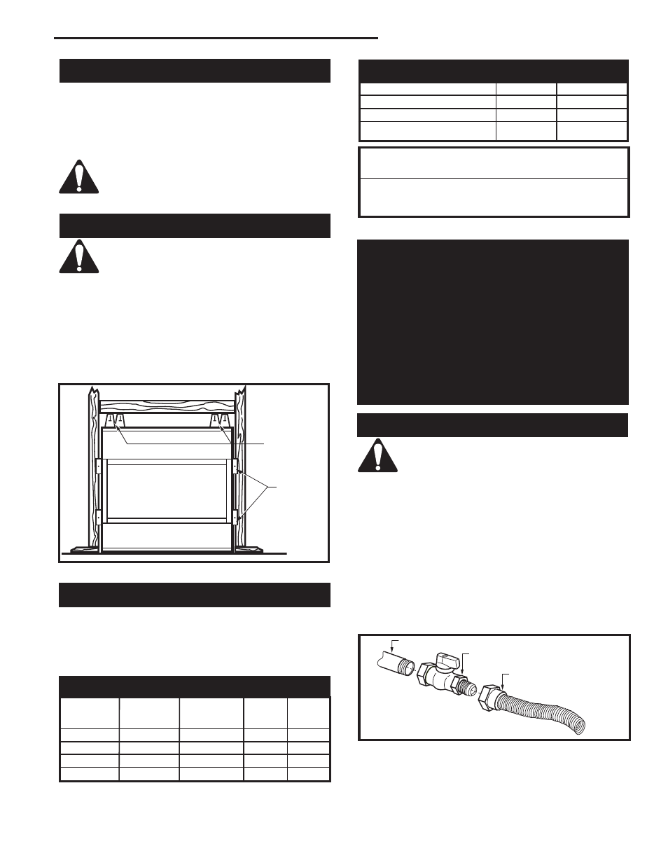
Gas Line Installation
When purging gas line the front glass must
be removed.
The gas pipeline can be brought in through the right
side of the appliance. Knockouts are provided at con-
venient locations to allow for the gas pipe installation
and testing of any gas connection.
The gas line connection can be made with 3/8” copper
tubing, 1/2” rigid pipe or an approved flex connector.
Since some municipalities have additional local codes,
it is always best to consult your local authority and the
CSA-B149.1 installation codes. For US installations
consult the current National Fuel Gas Code, ANSI
Z223.1/NFPA 54.
FP297A
INSTA VENT FREE
UVHB26 GAS SUPPLY
7/1/98
FP297A
Fig. 6 Typical gas supply installation.
1/2” Gas Supply
1/2” NPT X 1/2” Flare Shut-off Valve
3/8” Flex line
(from valve)