Cub Cadet 1345 SWE User Manual
Page 15
15
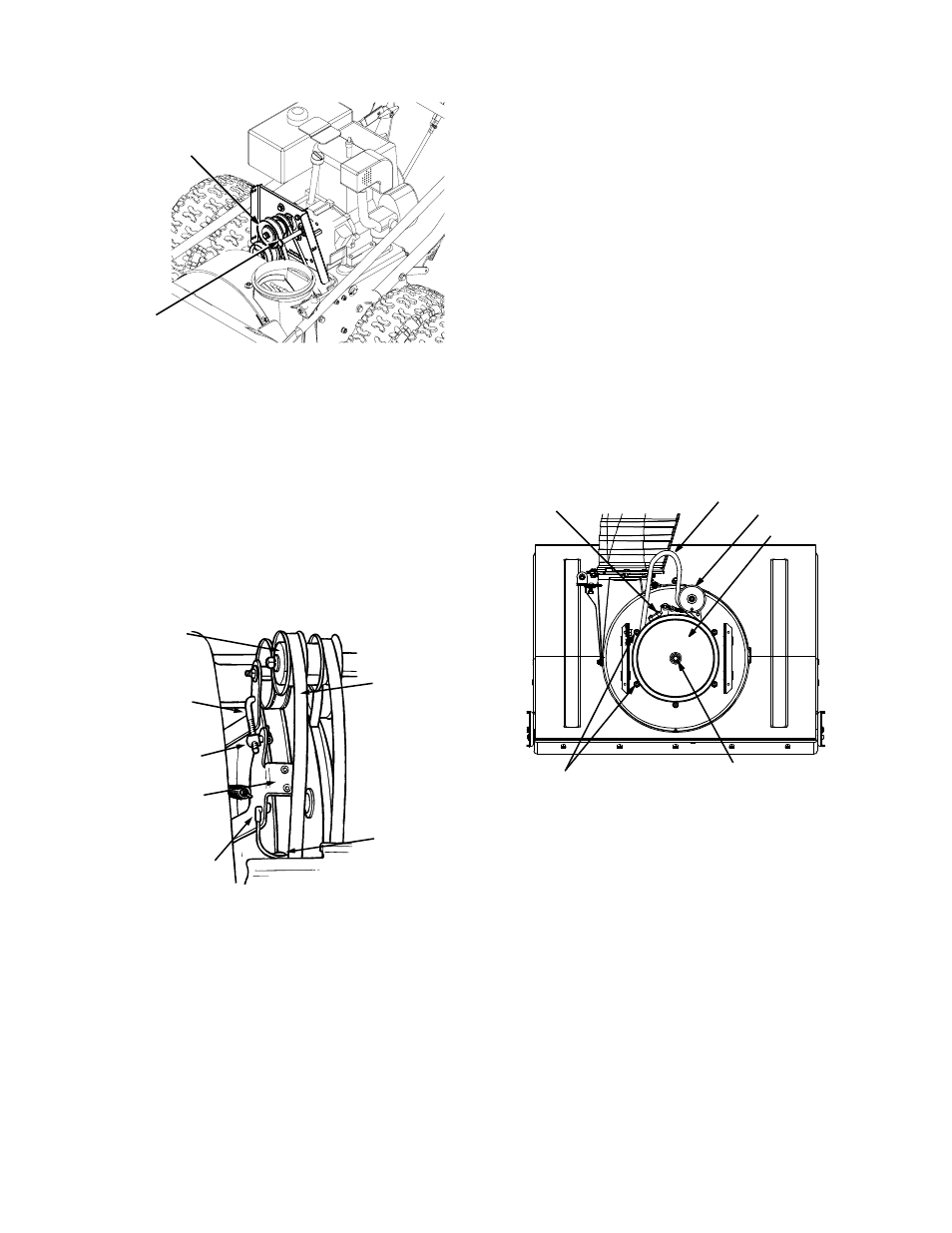
Figure 18
Auger Belt
•
Remove the cotter pin and washer from the ferrule
in order to disconnect the auger idler rod from the
brake bracket assembly as shown in Figure 19.
•
Slip the auger control belt (the front belt) off the
engine pulley. See Figure 19 .
•
Pull the brake bracket assembly towards the cable
guide roller and unhook the auger cable “Z” fitting.
•
Remove the upper bolts and lock washers which
attach the auger housing assembly to the frame
assembly using a 9/16” wrench. Refer to Figure 17.
Figure 19
•
Separate the auger housing from the frame
assembly by tilting the housing forward and pulling
up the handles.
•
Using a 1/2” wrench, remove the hex screw and
belleville washer from the center of the pulley on
the auger housing. Lift the brake bracket assembly
out of the pulley groove and remove the pulley. See
Figure 20. Be careful not to lose the key.
•
Remove and replace auger belt inside belt keepers.
•
Reassemble pulley to auger housing with hex
screw and belleville washer (cupped side toward
the pulley). Make sure key is in place on shaft and
brake puck is seated in the pulley groove.
•
Reassemble the belt cover and chute directional
control.
Proper Adjustment: With the auger clutch lever in the
disengaged position the top surface of the new belt
should be even with the outside diameter of the pulley.
•
To adjust, disconnect ferrule from brake bracket
assembly and thread ferrule in (towards idler) to
increase tension on belt, and out to decrease tension.
NOTE: The brake puck must always be firmly seated in
the pulley groove when the auger control is in the
disengaged position.
Figure 20
Drive Belt
•
Unhook the extension spring from the belt cover
plate. See Figure 21.
•
Remove drive belt from the engine pulley and
bottom drive pulley. Refer to Figure 21.
•
Replace belt and reassemble in reverse order.
•
Reassemble the two halves of the unit hooking the
lower portion of the auger housing over the
stationary shoulder bolts in the frame assembly.
•
Secure the two halves with the two bolts and lock
washers removed earlier. Refer to Figure 17.
Shoulder Bolt
Engine Pulley
Auger
Idler
Rod
Ferrule
Brake
Bracket
Assembly
“Z”
Fitting
Cable
Roller
Guide
Engine
Pulley
Auger
Control
Belt
Brake Bracket Assembly
Auger Belt
Hex Screw
Belleville Washer
Belt Keepers
Auger Pulley
Idler Pulley