Wiring typical wiring diagrams, Diagram 1 – Chromalox CES-6 User Manual
Page 4
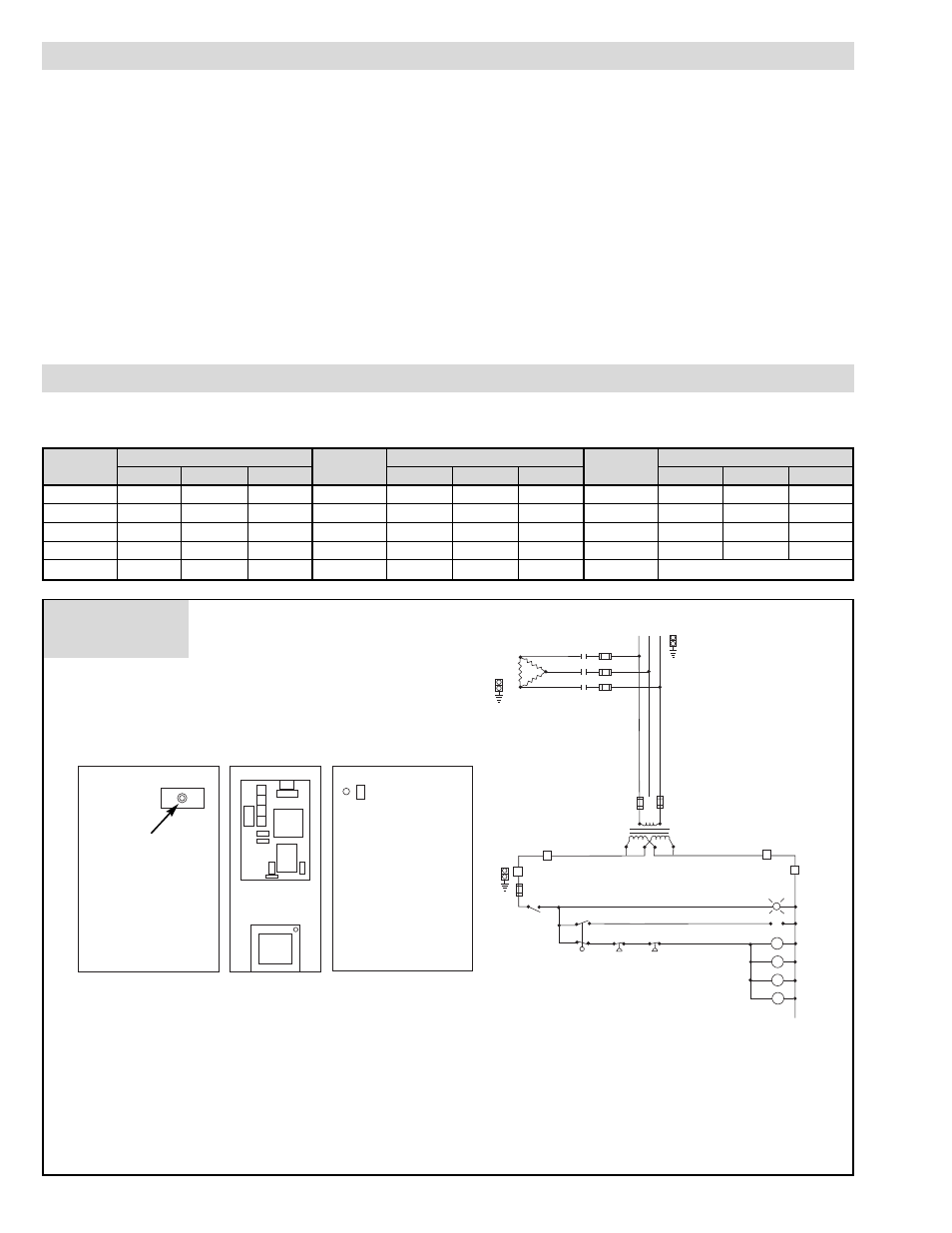
Diagram 1
3 Phase Voltage
3 Phase Voltage
3 Phase Voltage
Boiler
208
240
480
Boiler
208
240
480
Boiler
208
240
480
WIRING
TYPICAL WIRING DIAGRAMS
WARNING: Hazard of Electric Shock. Boiler must be
suitably grounded according to N.E.C. standard.
1. Be sure to use the proper wire. Electric wiring to boiler should be
in accordance with National Electrical Code or local wiring code
following wiring diagram supplied. (See recommendations on
safety switches and fusing.)
2. The unit is completely wired and pre-tested before shipment. No
internal wiring is required.
If a separate control circuit is used, the control circuit should be
connected to the control terminal block, inside access door (not
required with transformer).
3. Safety Switches — WARNING: Purchaser should use a
safety switch employing circuit breakers or fuses
between his main power source and the boiler.
4. Because of their water lines, boilers are susceptible to lightning
damage. Industrial type lightning protectors should be installed per
manufacturer’s recommendations at your service entrance. Check
your contractor or electrical dealer for recommended type for your
system.
5. Be sure all electrical connections are sufficiently tightened.
6. WARNING: Substitution of components or modifica-
tion of wiring system voids the warranty and may
lead to dangerous operating conditions.
7. SPECIAL INSTRUCTIONS FOR CUSTOMERS SUPPLY-
ING THEIR OWN CONDENSATE OR PUMP SYSTEMS.
A. Check the voltage of the motor before making the wiring con-
nection. Some Chromalox boilers are supplied with dual volt-
age systems. The motor should always match the voltage of the
control circuit.
B. The motor circuit should be wired into the pump control as
shown in wiring diagram (float type pump control). If boiler is
equipped with solid state pump control, refer to wiring diagram
and use terminals 5 and 2.
Use Applicable wiring diagrams based on model number and power voltage.
CES-6
1
1
1
CES-30
2
2
3
CES-100
8
8
9
CES-9
1
1
1
CES-36
2
2
3
CES-135
10
11
CES-12
1
1
1
CES-48
4
4
5
CES-160
12
13
CES-18
1
1
1
CES-60
6
6
7
CES-180
10
11
CES-24
2
2
3
CES-72
6
6
7
Export
14
2PS
BR
Heater
Contactors
Feed Water
Boiler On
3
GND
B
FU6
B 1PB
Off
1
GND
1
GND
1 HTR
C1
FU1
FU2
FU3
FU5
FU4
H1
H2
X1
X3
L3
1L1
1L3
1L2
L2
L1
X2
X4
Optional Transformer
1
1
C1
2
2
C4
C3
C2
R
1LT
Y
On
IFS
O
1PS
O
O
W
Feed Water
Electrical
Connection
2
1
1TB
1 2 3
3
GND
1
GND
2
GND
1
HTR
FU6
FU
1PB
Cabinet Exterior Left Side
Cabinet Exterior Right Side
Panel Layout
Wire Color Code
B
= Black
BR = Brown
R
= Red
O
= Orange
Y
= Yellow
G
= Green
BL = Blue
W = White
* Boilers under 40 Amps total (not fused)
4