OFM AA-610 User Manual
Model aa-610, Adjustable armrest for chair model 610, Assembly instructions
CAUTION:
1. Do not put excess pressure on arms while getting up
from, or sitting down in chair.
2. Check for loose screws and tighten them every 6 months.
Parts Listing
A
Washer
6 pcs.
B
M8 X 30mm Hex Screw
6 pcs.
C
Model AA-610
Adjustable Armrest
2 pcs.
Assembly Instructions
Tools Needed: Phillips Head Screwdriver
Please read all instructions before assembly.
Step 1: Turn Model 610 Chair upside down and place chair
on a clean, non-abrasive surface.
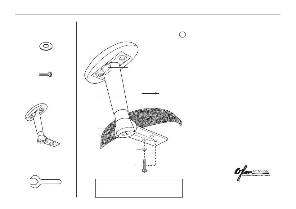
Step 2: Align the pre-drilled holes in the Model AA-610 Arms
(C) with the holes in the bottom of the chair seat, making
sure that the arms will be facing in the correct direction
when chair is in the upright position.
Step 3: Place five Washers (A) onto three M8 x 30mm Hex Screws
(B)
and insert through Model AA-610 Armrest
(C)
holes and into chair seat.
Step 4: Tighten screws using supplied Wrench (D) or
screwdriver. It is recommended that to assure screws
are secure that a screwdriver is used to tighten screws.
Step 5: Repeat steps 2, 3 and 4 for other arm rest
Step 6: Carefully turn chair over and place on the ground.
Step 7: To adjust the height of the arms, press the Height
Adjustment button located under the armrest, and
pull or push arm up or down. Release button to
lock into place.
B
Height Adjustment Button
Chair Seat
Facing Forward
D
Wrench
STOP
C
Holly Springs, NC, USA
800-520-7471 (voice)
919- 303-6389 (voice)
919-362-4765 (fax)
www.ofminc.com
Model AA-610
Adjustable Armrest for Chair Model 610
A
2007.06.11.A