Adjusting chart, Subsequent readjustment, Hex key needle adjustment – O.S. Engines 60B Carb - 27981010 User Manual
Page 2: Cleanliness, Parts list
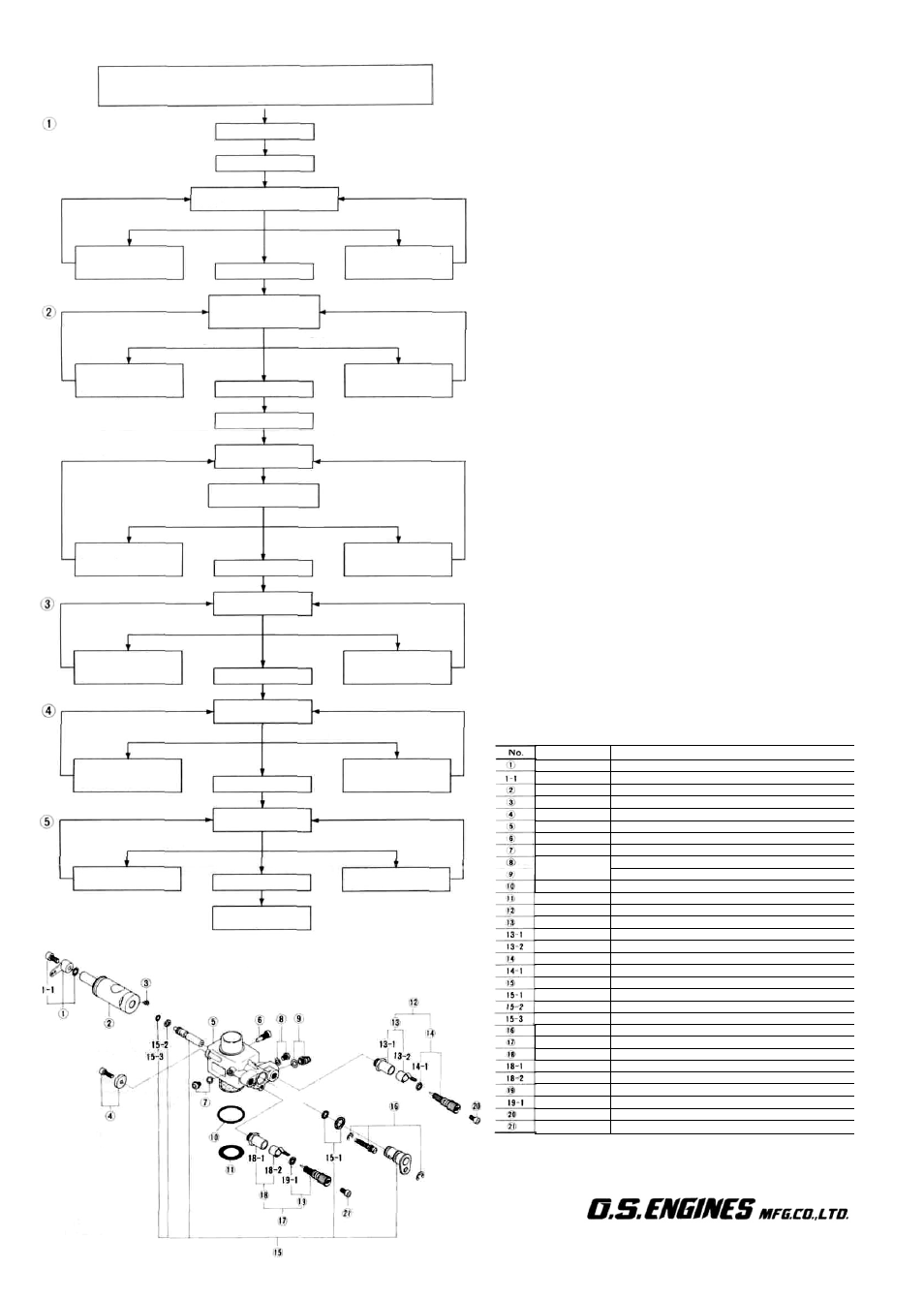
ADJUSTING CHART
High Speed Needle Valve—2 turns opened from fully closed position.
Medium Speed Needle Valve—1 turn opened from fully closed position
Idle Mixture Control S c r e w — 2 turns open from fully closed position
Start the engine
Warm up the engine
Medium Speed Needle Valve gradually until the optimum
hovering performance is obtained.
Note: It is NOT necessary to open the Medium Speed Needle Valve
if symptoms of lean running at hovering speeds remain
unconfirmed.
SUBSEQUENT READJUSTMENT
Once the engine has been run-in (see engine instructions) and the
carburettor controls properly set up, it should be unnecessary to
alter the mixture settings, except to make minor changes to the
Main (High-Speed) Needle Valve, occasionally, to take account
of differences in climatic conditions.
However, as previously mentioned, the use of a different fuel,
particularly one containing more, or less, nitromethane and/or
a different type or proportion of lubricating oil, is likely to call
for some modification to the High-Speed Needle Valve adjust-
ment. As a safety measure, it is advisable to increase the High-
speed Needle Valve setting by an extra half-turn counter-
clockwise prior to establishing the new setting. The same applies
if the silencer type is changed. A different silencer may alter the
exhaust pressure applied to the fuel feed and call for a revised
Needle-Valve setting.
The use of a different glowplug, or changes to the main rotor and
its pitch angles may also require compensating carburettor
readjustments.
HEX KEY NEEDLE ADJUSTMENT
The knurled heads of the two needle valves (High-speed and
Medium Speed) are provided with diagonal slots for use with a
s c r e w d r i v e r A l t e r n a t i v e l y for more positive location via an Allen
hexagonal key, these heads also have M2.6 internal threads, "into
which M2.6 x 6mm Allen cap-head screws may be fitted. To avoid
risk of damage to the fuel passages when tightening these screws,
remove the needle valves from the carburettor and use 'Loctite'
thread-lock compound to secure the screws.
CLEANLINESS
The minute particles of foreign matter that are invariably present
in any fuel, may result in a carburettor malfunction; most
commonly, restricted fuel flow, which may cause the engine to
cut out in flight, or to run lean, overheat and probably become
damaged. Be sure to use a good filter between your refuelling
container and the model's fuel tank.
O.S. 'Super-Filters' (large and small) are available as optional
extras. One of these, fitted to the outlet pipe inside your
refuelling container, will prevent the entry of foreign matter into
the fuel tank.
To clean the outside of the carburettor, use methyl-alcohol
(methanol) or glow fuel. Do not use gasoline, kerosene or other
petroleum based materials which may cause the silicone rubber
seals in the carburettor to swell and deteriorate.
PARTS LIST
Code No.
27381400
22826131
27981200
27981920
27981220
27981100
27981600
27881120
27881120
22681953
27915000
27915100
27981900
27381940
27381941
26711305
27981910
24981837
27981300
27981850
27881820
22781800
27981332
27981900
27381940
27381941
26711305
27981910
24981837
41621000
41621000
Description
Throttle Lever Assembly (w/Screw & Washer)
Throttle Lever Fixing Screw
Carburettor Rotor
Metering Nozzle Fixing Screw
Rotor Guide Washer (w/Fitting Screw)
Carburettor Body
Fixed Throttle Stop Screw
Plug Screw (w/Gasket)
Plug Screw (w/Gasket)
Fuel Inlet (w/Gasket)
Carburettor Rubber Gasket
Carburettor Sealing Washer
Needle Valve Assembly
Needle Valve Holder Assembly
Needle Valve Holder
Ratchet Spring
Needle (w/"0" Ring)
"0" Ring
Mixture Control Valve Assembly
"0" Ring Set
"0" Ring (L)
"0" Ring (S)
Mixture Control Screw (w/Retainer)
Needle Valve Assembly
Needle Valve Holder Assembly
Needle Valve Holder
Ratchet Spring
Needle (w/"0- Ring)
"0" Ring
Screw for Needle
Screw for Needle
The specifications are subject to alteration for improvement without notice
6-15 3-chome Imagawa Higashisumiyoshi-ku
Osaka 546, Japan. TEL (06) 702-0225
FAX. (06) 704-2722
Observe the mixture condition
while "floating" the model
Rich mixture
Lean mixture
Turn the Idle Mixture
Control Screw
counter-clockwise
Idling OK
Turn the Idle Mixture
Control Screw
clockwise
Observe the hovering
mixture condition
(Throttle response)
Lean mixture
Rich mixture
Close the High Speed
Needle Valve
(Turn clockwise)
Hovering OK
Open the High Speed
Needle Valve
(Turn counter-clockwise)
Land the model
Idle for approx:
10 seconds
Observe the transition
("Float" the model)
Lean mixture
Rich mixture
Turn the Idle Mixture
Control Screw
counter-clockwise
Idling OK
Turn the Idle Mixture
Control Screw
clockwise
High Speed Flight
Lean mixture
Rich mixture
Close the High Speed
Needle Valve
(Turn clockwise)
High speed flight OK
Open the High Speed
Needle Valve
(Turn counter-clockwise)
Lean mixture
Rich mixture
Turn the Idle Mixture
Control Screw
clockwise
Idling OK
Turn the Idle Mixture
Control Screw
counter-clockwise
Fine tuning of
idling mixture
Fine tuning of
hoverinq mixture
Rich mixture
Close the Medium
Speed Needle Valve
Hovering OK
Adjustment
completed
Open the Medium
Speed Needle Valve
Lean mixture
©Copyright 1992 by O.S. Engines Mfg. Co., Ltd. All rights reserved. Printed in Japan. 60130260-19706