Installation, Parts list – O.S. Engines 40C Carb - 25683000 User Manual
Page 4
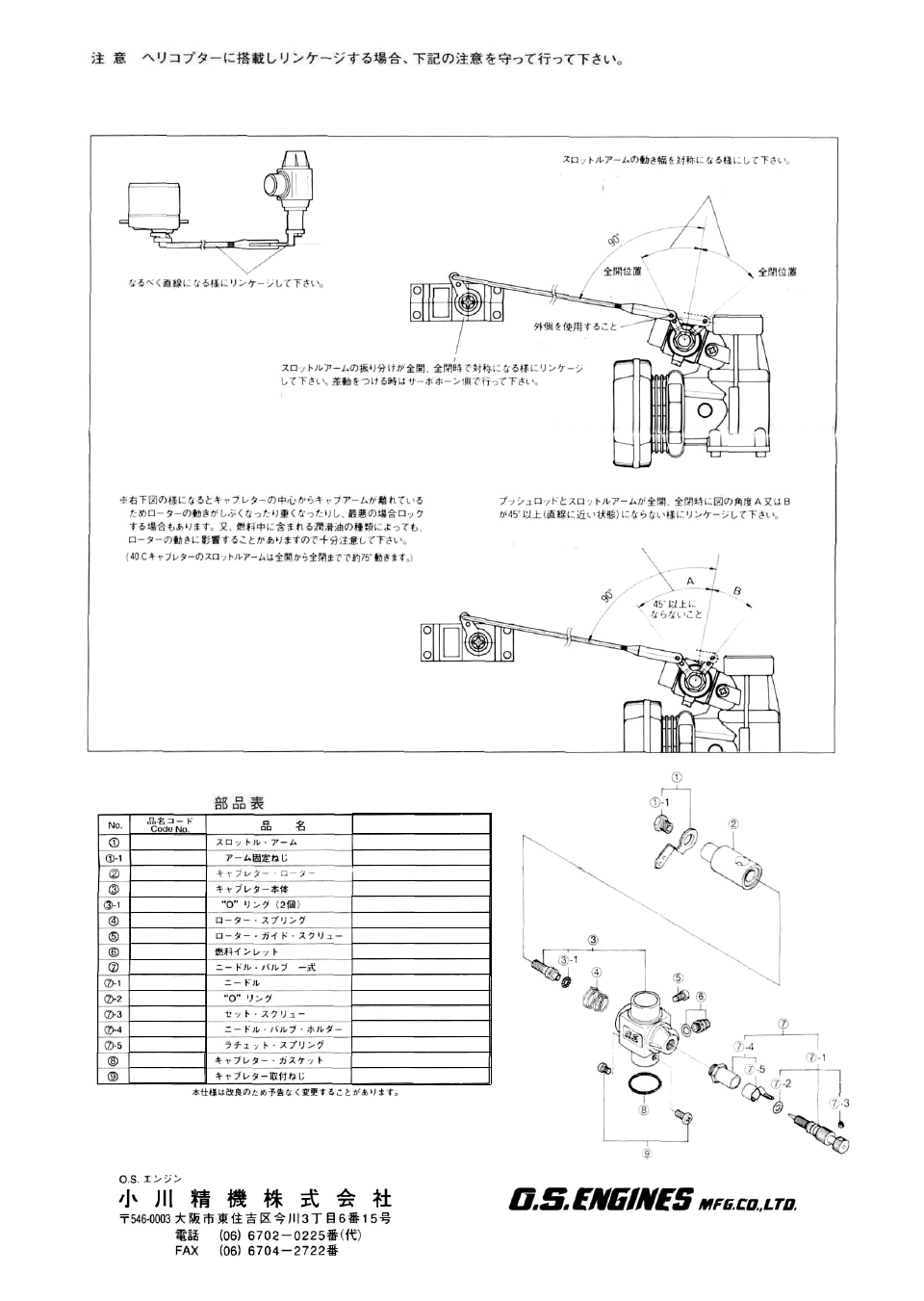
INSTALLATION
After fitting the engine in the helicopter, please observe the following recommendations when linking the throttle servo to the
carburettor.
CORRECT-Throttle lever movement should be
disposed symmetrically, as shown
Locate the servo so that its output arm and the
throttle pushrod are. as closely as possible, di-
rectly in line with the carburettor's throttle arm, as
shown.
Fully closed
position
Note If differential throttle movement is required, make necessary
adjustment at the servo output arm, not at the throttle lever.
When the throttle is fully open or fully closed, the
throttle lever angle should not be more than 45° either
side of the mid-point of its travel (and where it is at a
90' angle to the pushrod), otherwise throttle rotor move-
ment may become inhibited or may even lock up.
Also, some lubricants may affect the throttle rotor
movement.
Please note that the throttle lever angles of the O.S.
Type 40C carburettor are well within these limits
-requiring only 75° from the fully open to fully closed
positions.
INCORRECT -One-way throttle lever movement should not
be more than 45° \
Use outer hole.
Fully open
position
PARTS LIST
Description
Throttle Lever
Throttle Lever Fixing Screw
Carburettor Rotor
Carburettor Body
"0" Ring
Rotor Spring
Rotor Guide Screw
Fuel Inlet
Needle Valve Assembly
Needle
"0" Ring
Set Screw
Needle Valve Holder
Ratchet Spring
Carburettor Gasket
Carburettor Fixing Screw
The specifications are subject to alteration for improvement without notice.
6-15 3-Chome Imagawa Higashisumiyoshi-ku
Osaka 546-0003, Japan TEL. (06) 6702-0225
FAX. (06) 6704-2722
22781 410
2 2781 420
2 5683 200
25683100
2 4881 824
2 6781 506
4 5581 820
2 2681 953
2 7881 900
2 4981 959
2 4981 837
2 6381 501
2 7381 940
2 6711 305
46215000
2 5081 700
© Copyright 1996 by O.S. Engines Mfg. Co.. Ltd. All rights reserved. Printed in Japan.
60130340-19907