O.S. Engines 7M Carb - 27481000 User Manual
Page 2
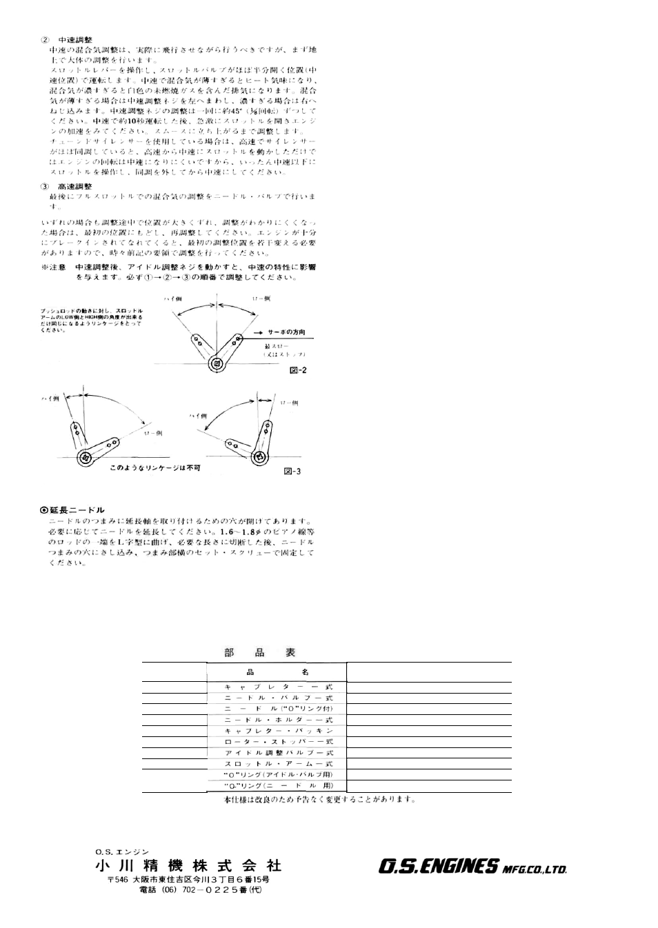
INCORRECT THROTTLE LEVER THROW
Fig-3
Do not turn the Idle Mixture Control Screw more than 15 degrees at
a time and do not touch either of the other two mixture control
screws at this stage.
2) Correct mid-range mixture strength is best confirmed by actual
flight tests. However, preliminary adjustment, prior to flight, car be
established in the following manner:
Set the throttle approximately half open.
If the mixture is too rich, this will be indicated by an excessively
smoky exhaust. To correct these conditions, turn the Mid-Range
Mixture Control Screw in a clockwise direction. If, on the other
hand, the mixture is too lean, the engine may overheat and lose
power if running is prolonged. This condition should be corrected
by turning the Mid-Range Mixture Control Screw in a counter-
clockwise direction. Do not rotate the screw excessively: steps of
about 45 degrees are best.
Check acceleration or 'pick-up' by opening the throttle abruptly
after the engine has been running at half-throttle for not less than
10 seconds. Fine-tune the Mid-Range Mixture Control Screw to
achieve the desired response.
If the engine is equipped with a tuned silencer, closing the throttle
from full-throttle to half-throttle may not produce the required
level of speed reduction, due to the effect of the tuned silencer. In
this case, close the throttle below the half-throttle position to bring
the silencer 'out of tune', then re-open it to the required mid-range
speed.
3) Finally, adjust the Needle-Valve in the normal manner at full
throttle. It is customary to set the needle-valve a little on the rich
side of the setting at which maximum rpm are reached.
Remember that, with all three controls, clockwise rotation makes
the mixture weaker or 'lean' (ultimately resulting in a tendency to run
hot or cut out) while counter-clockwise rotation makes the mixture
progressively richer (indicated by a smoky exhaust or uneven running).
However, if you become confused through turning an adjustment too
far, simply re-set the control in accordance with the recommended
'Provisional Settings' paragraph and begin adjustment again.
After the engine is fully run-in and/or when a different fuel is used.
it may be necessary to change the screw positions very slightly.
THROTTLE STOP SCREW
Rotate this screw to obtain the required idling speed: counter-clockwise
to reduce idling speed, clockwise to increase idling speed. The adjust-
ment can be held firmly by gently tightening the locknut.
THROTTLE LEVER
Three different throttle arms are provided. Fit the one most appro-
priate to your installation.
NEEDLE-VALVE EXTENSION
The needle-valve fitted to this carburettor is designed to accept an ex-
tension arm so that, when the engine is enclosed within a fuselage, the
needle-valve may be adjusted from the outside. An L-shaped steel wire
rod of approximately 1.6 mm (or 1/16") dia. and appropriate length,
should be inserted into the centre-hole and secured by tightening the
set-screw in the control-knob with the small Allen key wrench provided.
Low
High
Low
High
Set linkage so that the angles of
the low side and the high side of
the throttle lever throw are
equal.
Low
Fig-2
High
PARTS LIST
Description
Carburettor Complete
Needle Valve Assembly
Needle (with 0 ring)
Needle Valve Holder Ass'y
Carburettor Rubber Gasket
Throttle Stop Screw Assembly
Idle Adjusting Valve Assembly
Throttle Lever Assembly
0 Ring (for Idle Valve)
0 Ring (for Needle)
if&« =1 - K |
Code No.
27481000
27481900
45581970
27381940
29015019
27181600
27381301
27481400
24881824
24981837
The specification is subject to alteration for improvement without notice.
6-15 3-chome Imagawa Higashisumiyoshi-ku
Osaka 546, Japan. TEL. Osaka (06) 702-0225