Carburettor cleanliness, Realignment of idle valve (mixture control valve) – O.S. Engines 2D Carb - 22481045 User Manual
Page 2
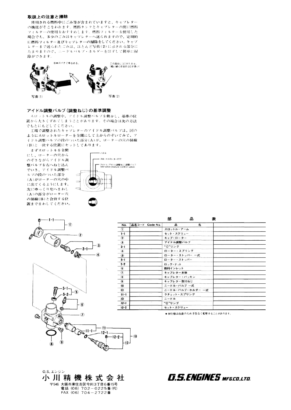
Dirt and fibrous matter
mostly accumulate here
As with all engines, it is advisable to set both valves slightly
on the rich side of the best rpm setting, as a safety measure.
10) When the mixture has been corrected, the idling speed will
probably increase. Readjust the throttle opening by means
of the throttle trim on the transmitter, or by screwing out
the throttle-stop screw, so that the lowest possible idling
speed, without stopping the engine, may be obtained. Adjust
the throttle-stop screw so that the engine stops (the throttle
fully closed) when the throttle trim is at the lowest position.
CARBURETTOR CLEANLINESS
The correct functioning of the carburettor depends on its small
fuel orifices remaining clear. The minute particles of foreign
matter that are present in any fuel can easily partially obstruct
these orifices and upset mixture strength so that engine per-
formance becomes erratic and unreliable.
It is recommended that fuel is passed through a filter when the
tank is filled and that a good in-line filter is installed between the
fuel tank and carburettor and, furthermore, that this filter is
frequently cleaned to remove dirt and lint that accumulates on
the filter screen. Finally, occasionally remove the needle-valve
holder from the carburettor as shown in Photo ( 1 ) and extract
any remaining foreign matter that may have lodged in the loca-
tion shown in Photo (2).
REALIGNMENT OF IDLE VALVE
(MIXTURE CONTROL VALVE)
In the course of making carburettor adjustments, it is just
possible that the idle valve may be inadvertently screwed in or
out too far and thereby moved beyond its effective adjustment
range. Its basic setting can be re-established as follows:
With the throttle fully open, the position of the idle valve can be
seen by looking into the intake. The basic (factory) setting is as
shown in the main sketch, i.e. with the shoulder portion 'A'
exactly at a tangent to the throttle rotor hole.
To return the idle valve to its original position, first screw in the
idle valve, while looking into the rotor hole, until the shouldered
portion comes into view — see small sketch. Then gradually un-
screw the idle valve until 'A' is precisely tangential to the rotor
hole (i.e. so that 'A' and 'B' are superimposed) as in the main
sketch.
Photograph (1)
Photograph (2)
Remove this with
an 8mm spanner
Nozzle
Throttle rotor hole
A
B
• The above specifications are subject to change without notice for improvement.
22481400
26381501
26781200
26781309
24881824
26781506
22481300
22481310
22481320
22681953
24481150
22615000
23081706
24981930
26781965
26711305
24981959
24981837
26381501
Description
Throttle Lever
Set-screw
Carburettor Rotor
Mixture Control Valve
"0" Ring
Rotor Spring
Rotor Stop Set Screw Assembly
Rotor Stop
Rock Nut
Fuel Inlet
Carburettor Body
Carburettor Rubber Gasket
Carburettor Fixing Screw
Needle Valve Assembly
Needle Valve Holder Assembly
Ratchet Spring
Needle
"0" Ring
Set-screw
6-15 3-chome Imagawa Higashisumiyoshi-ku
Osaka 546, Japan. TEL. (06) 702-0225
FAX. (06) 704-2722
© Copyright 1988 by O.S. Engines Mfg. CO., Ltd. All rights reserved. Printed in Japan.
38909