Relocation of carburetor controls, Choke valve, Installation fuel tank – O.S. Engines FS-120S-E User Manual
Page 4
6
The needle-valve and throttle lever locations are
interchangeable by reversing the carburetor. This can be
done as follows:
Remove the carburetor carefully by unscrewing the two
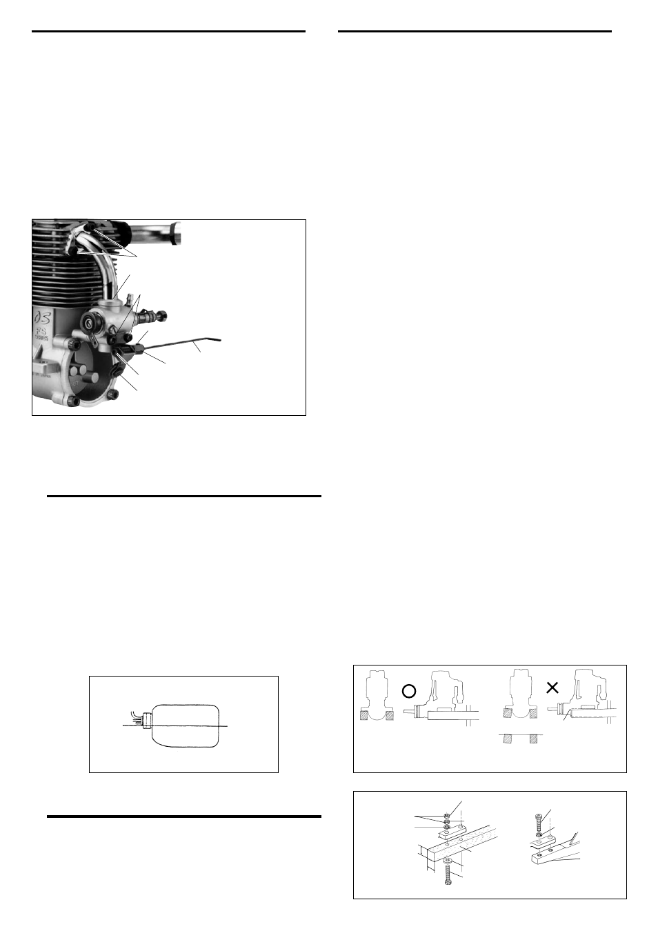
screws which secure both carburetor and choke valve. (See
Photo 1.)
If the carburetor remains difficult to remove, slightly loosen the
two screws which secure the intake pipe to the cylinder head.
After reversing the carburetor, re-fit it to the intake pipe gently,
taking care not to damage the O-ring in the carburetor by
using foce.
RELOCATION OF CARBURETOR CONTROLS
Intake Pipe Retaining Screw
"O" Ring
Carburetor Retaining Screw
Choke lever
Set screw
Hexagon nut
Cap screw
Choke rubber pad
Photo 1
CHOKE VALVE
The FS-120S-E is equipped with a spring-loaded choke valve.
The choke valve operating lever can be located right or left by
transposing the hexagon nut and cap screw.
After mounting the engine in the model, secure the L-shaped
choke rod by tightening the set-screw.
If the rod supplied is too long, reduce it to the required lebgth.
If the rod length is more than 40mm (1 1/2 in.) its outer end
should be supported to avoid vibration.
7
Because the FS-120S-E powerful, large-displacement, single-
cylinder four-stroke-cycle engines, it is essential to use very
substantial engine mounting. Conventional wooden mounting
beams should be of rigid hardwood and of at least 15mm or
5/8-in square section.
INSTALLATION
FUEL TANK
The suggested fuel tank size is 400cc or 14 oz. This will give
approximately 10 minutes running time when some part-
throttle operation is included. Locate the fuel tank so that the
centre line of the tank is 10 to 15mm below the centre line of
the needle-valve.
Make sure that the mounting beams are parallel and that their top
surfaces are in the same plane.
How to fasten the mounting screws.
Hardwood mounting beams
O.S. radial motor mount
(cast aluminum)
Tighten second nut firmly
down onto first nut.
Tighten this nut first.
Steel washer
5mm steel nuts
5mm steel screw
Spring washer or
lock washer
15mm min.
15mm min.
Hardwood such as
cherry or maple.
Spring washer
5mm steel Allen screw
Make sure that these mounting beams are accurately aligned
and firmly integrated with the airframe, reinforcing the
adjacent structure to absorb vibration. Use 5mm or larger
steel screws, preferably Allen type hexagon socket head cap
screws, with washers and locknuts, for bolting the engine to
the bearers. As an alternative to wooden beam mounting, a
special O.S. cast aluminium radial motor mount, complete with
5mm mounting screws, is available as an optional extra part
(Code No.71904200) , where front bulkhead (firewall) type
mounting is called for. Engine installation should, in any case,
be made in such a way that basic maintenance can be
conveniently carried out.
Front view
CORRECT
Side view
Top surfaces are in the same plane.
Re-align the surfaces
as necessary
INCORRECT
Top surfaces are not
in the same plane.
Opposite beam
Top surfaces are not
in the same plane.
Engine does not
rest firmly.
NOTE
If the model is left unattended with the fuel tank filled,
fuel may flow into the carburetor, causing it to "flood"
and making the engine difficult to start. Take appropriate
action to prevent this.
Centre line