Needle-valve location basic engine parts, Installation of the engine – O.S. Engines 46AX User Manual
Page 5
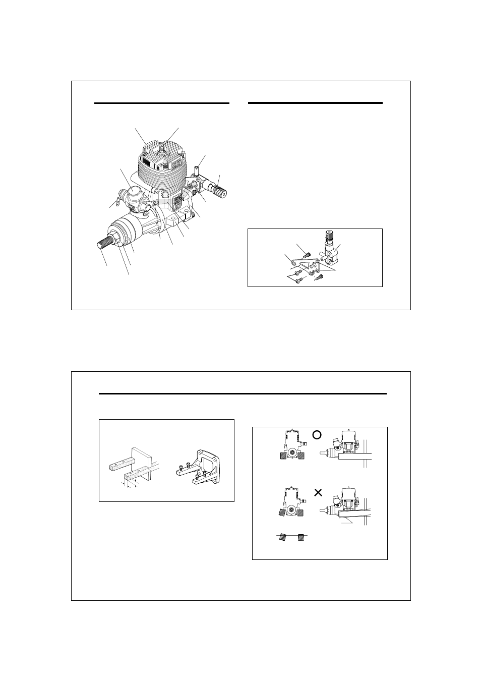
8
NEEDLE-VALVE LOCATION
BASIC ENGINE PARTS
Cylinder head
Carburetor
Silicone Tube
Crankshaft
Propeller nut
Propeller washer
Drive Hub
Crankcase
Needle valve
Cover Plate
Fuel outlet
Fuel inlet
Glowplug
Fuel inlet
Beam Mount
Throttle
Lever
The procedure for relocating the needle-valve is as
follows:
Finally, secure the complete assembly to rear cover
plate as before.
3.
As self-tapping screws are used for unit
attachment, screw them in carefully so that screw
threads match those of the unit body precisely.
Note:
Remove the two cover-plate screws which secure
the needle-valve assembly bracket, then carefully
remove the two screws by which the needle-valve
unit is attached to the bracket.
Rotate the needle-valve unit through 90˚ and re-
attach it to the bracket in the required position (see
sketch right ).
Vertical position
(Factory position)
Cover plate fitting holes
Needle Valve unit
Needle Valve unit
attachment screws
Needle-Valve
Assembly Bracket
1.
2.
Cover plate Retaining Screw
9
INSTALLATION OF THE ENGINE
Rigid hardwood
(e.g. maple)
At least
15mm(5/8")
At least
15mm(5/8")
O.S. radial motor mount
(Available as an optional extra
part. See parts list)
A typical method of beam
mounting is shown below, left.
Installation in the model
For 46AX, 50SX, 40/46FX (Code No. 71913100)
Make sure that the mounting beams are parallel and
that their top surfaces are in the same plane.
Front view
Side view
Top surfaces are not
in the same plane.
Opposite
beam
Top surfaces are not
in the same plane.
Re-align the surfaces
as necessary
Engine does not rest firmly.
CORRECT
INCORRECT
Top surfaces are in the same plane.
O.S. radial motor mount